DAK-85 Power Integrations, DAK-85 Datasheet - Page 15
DAK-85
Manufacturer Part Number
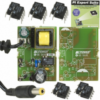
DAK-85
Description
DESIGN ACCELERATOR KIT LP SWITCH
Manufacturer
Power Integrations
Series
LinkSwitch®-LPr
Specifications of DAK-85
Main Purpose
AC/DC, Primary Side
Outputs And Type
1, Isolated
Power - Output
2W
Voltage - Output
6V
Current - Output
330mA
Voltage - Input
90 ~ 265VAC
Regulator Topology
Flyback
Frequency - Switching
66kHz
Board Type
Bare (Unpopulated) and Fully Populated
Utilized Ic / Part
LNK562, LNK563, LNK564
Lead Free Status / RoHS Status
Lead free / RoHS Compliant
Other names
596-1104
Available stocks
Company
Part Number
Manufacturer
Quantity
Price
Company:

Part Number:
DAK-85
Manufacturer:
Power Integrations
Quantity:
135


Note: Gap size was verified with transformer vendor as being acceptable. Higher flux
density resulted in peak audible noise of <35 dBA without enclosure, also acceptable as
a further 10 dB reduction is typical once inside sealed enclosure.
Page 15 of 32
R2
Recommended Bias Diode
DC INPUT VOLTAGE PARAMETERS
VMIN
VMAX
CURRENT WAVEFORM SHAPE PARAMETERS
DMAX
IAVG
IP
IR
IRMS
TRANSFORMER PRIMARY DESIGN PARAMETERS
LP
LP_TOLERANCE
NP
ALG
BM
BAC
ur
LG
BWE
OD
INS
DIA
AWG
CM
CMA
TRANSFORMER SECONDARY DESIGN PARAMETERS
Lumped parameters
ISP
ISRMS
IRIPPLE
CMS
AWGS
DIAS
ODS
INSS
VOLTAGE STRESS PARAMETERS
VDRAIN
PIVS
5.00
Info
Warning
1N400
2738 uHenries
1922 Gauss
1654
3.00 k-ohms
0.48
0.04 Amps
0.12 Amps
0.12 Amps
0.05 Amps
0.08 mm
17.2 mm
0.16 mm
0.04 mm
0.12 mm
1.68 Amps
0.65 Amps
0.56 Amps
0.32 mm
1.08 mm
0.38 mm
375 Volts
108
233 nH/T^2
801 Gauss
374 Cmils/Am
130 Cmils
80 Volts
37 AWG
20 Cmils
28 AWG
34 Volts
3
5 %
- Volts
p
Minimum DC Input Voltage
Maximum DC Input Voltage
Maximum Duty Cycle
Average Primary Current
Minimum Peak Primary Current
Primary Ripple Current
Primary RMS Current
Typical Primary Inductance. +/- 5%
Primary inductance tolerance
Primary Winding Number of Turns
Gapped Core Effective Inductance
!!! Info. Flux densities above ~ 1500 Gauss may produce
audible noise. Verify with dip varnished sample transformers.
Increase NS to greater than or equal to 11 turns or increase
VOR
AC Flux Density for Core Loss Curves (0.5 X Peak to Peak)
Relative Permeability of Ungapped Core
!!! INCREASE GAP>>0.1 (increase NS, decrease VOR,bigger
Core
Effective Bobbin Width
Maximum Primary Wire Diameter including insulation
Estimated Total Insulation Thickness (= 2 * film thickness)
Bare conductor diameter
Primary Wire Gauge (Rounded to next smaller standard AWG
value)
Bare conductor effective area in circular mils
Primary Winding Current Capacity (150 < CMA < 500)
Peak Secondary Current
Secondary RMS Current
Output Capacitor RMS Ripple Current
Secondary Bare Conductor minimum circular mils
Secondary Wire Gauge (Rounded up to next larger standard
AWG value)
Secondary Minimum Bare Conductor Diameter
Secondary Maximum Outside Diameter for Triple Insulated
Wire
Maximum Secondary Insulation Wall Thickness
Peak Drain Voltage is highly dependent on Transformer
capacitance and leakage inductance. Please verify this on the
bench and ensure that it is below 650 V to allow 50 V margin for
transformer variation.
Output Rectifier Maximum Peak Inverse Voltage
Tel: +1 408 414 9200 Fax: +1 408 414 9201
Power Integrations
www.powerint.com
Related parts for DAK-85
Image
Part Number
Description
Manufacturer
Datasheet
Request
R

Part Number:
Description:
KIT DESIGN ACCELERATOR MODEM
Manufacturer:
Power Integrations
Datasheet:

Part Number:
Description:
KIT DESIGN ACCELERATOR SET TOP
Manufacturer:
Power Integrations
Datasheet:

Part Number:
Description:
KIT REF DES DPA 6.6W DC-DC CONV
Manufacturer:
Power Integrations
Datasheet:

Part Number:
Description:
KIT DESIGN ACCELERATOR POE CONV
Manufacturer:
Power Integrations
Datasheet:

Part Number:
Description:
DESIGN ACCELERATOR KIT XT SWITCH
Manufacturer:
Power Integrations
Datasheet:

Part Number:
Description:
KIT DESIGN ACC PEAKSWITCH FAMILY
Manufacturer:
Power Integrations
Datasheet:

Part Number:
Description:
KIT DESIGN ACCELERATOR ADAPTER
Manufacturer:
Power Integrations
Datasheet:

Part Number:
Description:
KIT DESIGN ACCELERATOR ADAPTER
Manufacturer:
Power Integrations
Datasheet:

Part Number:
Description:
KIT DESIGN ACCELERATOR DC-DC
Manufacturer:
Power Integrations
Datasheet:

Part Number:
Description:
KIT DESIGN ACCELERATOR DPA SW
Manufacturer:
Power Integrations
Datasheet: