© 2004 National Semiconductor Corporation
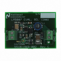
LM5007 Evaluation Board
Introduction
The LM5007 evaluation board is designed to provide the
design engineer with a fully functional step down switching
regulator to evaluate LM5007 regulator IC,in a typical envi-
ronment.
The performance of evaluation board is as follows:
• Input range: 12V to 75V
• Output voltage: 10V
• Output current: 400mA
• Measured efficiency: 90% at 300mA and V
• Board size: 31.9mm x 44.4mm
Theory Of Operation
The LM5007 Step down switching regulator features all of
the functions needed to implement low cost, efficient, Buck
bias regulators. This high voltage regulator contains an 80V,
0.7A N-channel Buck switch. The regulator is based on
hysteretic control scheme using an on-time inversely propor-
tional to input voltage (V
frequency to remain relatively constant with load and input
voltage voltage variations. The hysteretic control requires no
control loop compensation, while providing fast load tran-
sient response. Additional protection features include : Ther-
mal Shutdown, V
ty–cycle limiter. LM5007 can be used in numerous
applications to efficiently regulate step down higher voltage
inputs. This regulator is well suited for 48V telecom and the
new 42V automotive power bus ranges.
The LM5007 operates in discontinuous conduction mode at
light load currents or continuous conduction mode at heavier
load currents. In discontinuous conduction mode, current
through the output inductor starts at zero and ramps up to
the peak value during the buck switch on time, and then back
to zero during buck switch off time. In discontinuous conduc-
tion mode, the operating frequency can be relatively low and
will vary with load. Therefore at light loads the conversion
efficiency is maintained , since switching losses decrease
with reduction in switching frequency.
CC
undervoltage lockout and maximum du-
IN
). This feature allows the operating
AN200832
IN
= 30V
National Semiconductor
Application Note 1298
Ravi Murugeshappa
January 2004
The evaluation board just needs one high voltage power-
supply (upto 75V and current rating of 1A). The maximum
output power is 4 watts. Either an electronic load or resistor
bank can be used for testing evaluation board.
Start-up Feature
There is no soft-start feature in LM5007, and it normally
comes up with full load current to supply the power de-
manded by the load within a short time.The LM5007 con-
tains an intelligent current limit OFF timer intended to reduce
the foldback characteristic inherent with fixed off-time over-
current protection. If the current in the Buck FET exceeds
725mA the present cycle is immediately terminated (cycle by
cycle current limit). Following the termination of the cycle a
non-resetable current limit off timer is initiated. The duration
of off time is a function of the external setting resistor (Rcl)
and the FB pin voltage. When FB pin voltage = 0V the
current limit off time is internally preset to 15µs. This condi-
tion occurs in short circuit operation when a maximum
amount of off time is required.
In cases of overload (not complete short circuit) the current
limit off time can be reduced as a function of the output
voltage (measured at the FB pin). Reducing the off time
during smaller overloads reduces the amount of foldback
and also reduces the initial start-up time.
Low Ripple Configuration
For applications where lower output voltage ripple is re-
quired the output load can be connected directly to the low
ESR output capacitor, as shown below. The evaluation board
is laid out in such a way that, user can use either (high ripple
or low ripple) options by simply shifting the output connector.
The series resistor (R) will degrade the load regulation how-
ever. Another technique for enhancing the ripple voltage at
the FB pin is to place a capacitor in parallel with the feedback
divider resistor R1. The addition of the capacitor reduces the
attenuation of the ripple voltage from the feedback divider.
www.national.com