MULTIPHSPOL-RD Silicon Laboratories Inc, MULTIPHSPOL-RD Datasheet
MULTIPHSPOL-RD
Specifications of MULTIPHSPOL-RD


Related parts for MULTIPHSPOL-RD

MULTIPHSPOL-RD Summary of contents
Page 1
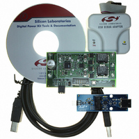
Si825 Kit Contents The non-isolated Si825x Multi-Phase Point of Load (POL) Reference Design contains the following items: 40 Amp Si8250-based Multi-Phase POL Target Board ™ USB to ...
Page 2
Si825x Multi-Phase POL-RD 2. Hardware Overview The Si825x Multi-Phase POL Reference Design implements a digitally-controlled POL with a DPWM (digital pulse width modulation) switching frequency of 391 kHz. The Si8250 Multi-Phase POL Target Board (Figure 1) contains system power stages ...
Page 3
Si8250 Multi Phase POL Target Board Stand-Alone Operation The POL target board comes preloaded with firmware algorithms, and is designed to provide a 3.3 V output with Amps of output current. To operate the target board ...
Page 4
Si825x Multi-Phase POL-RD 4. Development/Debug Operation: Initial Hardware Setup This section describes the use of the Si8250 Multi-Phase POL Target Board with the Silicon Laboratories integrated development environment (IDE) and Application Builder tools. To configure the hardware for connection to ...
Page 5
Development/Debug Operation: Software Setup The Si825x Multi-Phase POL Reference Design comes with Application Builder software (detailed in "8. Si825x Application Builder” on page 12), a configurable real-time software Kernel, and a software Kernel compiled specifically for the Si8250 Multi-Phase ...
Page 6
Si825x Multi-Phase POL-RD 7. Download the project to the target by clicking the Download Code button in the toolbar. Note: To enable automatic downloading if the program build is successful, select Enable automatic connect/download after build in the Project→Target Build ...
Page 7
PMBus Operation PMBus is a connectivity solution designed for networking multiple power supplies using a single management bus. The Real-time Kernel provided with the Si825x Multi-Phase POL Reference Design includes optional support for PMBus. In addition, the Si825x POL ...
Page 8
Si825x Multi-Phase POL-RD 7. Open the Application Builder by selecting Silicon Laboratories→Si825x Application Builder from the PC programs menu. 8. Run the PMBus Monitor application by selecting Options→Launch PMBus Monitor Tool from the Application Builder. The window shown in Figure ...
Page 9
Silicon Laboratories Integrated Development Environment The Silicon Laboratories IDE combines an editor, project manager, code development tools, and a debugger into a single intuitive environment for code development and in-system debugging. No additional target RAM, program memory, or communications ...
Page 10
Si825x Multi-Phase POL-RD 7.3. Evaluation C51 C Compiler An evaluation version of the Keil C51 C compiler is included with the development kit and is installed during IDE installation. The evaluation version of the C51 compiler is the same as ...
Page 11
When finished with the debug session, save the project to preserve the current target build configuration, editor settings, and the location of all open debug views. To save the project, select Project→Save Project As... from the menu. Create a ...
Page 12
Si825x Multi-Phase POL-RD 8. Si825x Application Builder In addition to the IDE, the Si825x family is supported with an intuitive toolset that leverages traditional power supply control design methods minimizing the digital supply design learning curve. The toolset consists of ...
Page 13
DPWM Timing Diagram Editor The DPWM Timing Diagram Editor permits designers to generate DPWM initialization code by simply drawing the timing for their end system. The wizard accommodates up to six output phases and can be used to establish ...
Page 14
Si825x Multi-Phase POL-RD Figure 10. DPWM Timing Diagram Editor—Phase 2 3. Click the Simulate button to display the Simulate Window (see Figure 11). Use the arrows to increase and decrease the value of u(n). Notice that Phase 1’s edge should ...
Page 15
Compensation Editor The Compensation Editor is a loop simulation and coefficient generator tool for frequency compensating the system. To open the Compensation Editor window, open the Application Builder and select System Configuration→Compensation Editor from the menu. The Compensation Editor ...
Page 16
Si825x Multi-Phase POL-RD 8.3. System Parameter Programmer The System Setting Programmer allows the designer to input all system settings (UVLO, OV, OCP, etc.) and then converts these parameters to HEX and populates the resulting initialization code in the Kernel. To ...
Page 17
Peripheral Configuration Wizard The Peripheral Configuration Wizard can be used to automatically generate initialization code for the Si825x’s on- chip peripherals (ADC2, comparator, UART, SMBus on the Peripherals menu in the Application Builder. Figure 14 illustrates the Port I/O ...
Page 18
Si825x Multi-Phase POL-RD 9. Restoring Factory Defaults The Si825x Multi-Phase POL Reference Design includes hex files created for the multi-phase POL application. Downloading these hex files to the Si8250 Multi-Phase POL Target Board will restore the board to its factory ...
Page 19
Si8250 Multi-Phase POL Target Board The Si8250 Multi-Phase POL Target Board has a Si8250-IQ installed. Refer to Figure 15 for the locations of the various I/O connectors and major components. J1, J2 VIN, Supply Input power connection 10-15 V, ...
Page 20
Si825x Multi-Phase POL-RD 10.2. Switches and LEDs One switch is provided on the target board. Switch S1 is connected to the RESET pin of the Si8250. Pressing S1 puts the Si8250 device into its hardware-reset state. Two LEDs are also ...
Page 21
SMBus Connector (J6) The J6 connector is the SMBus interface connector for the Si8250 Multi-Phase POL Target Board. Table 6 shows the J6 pin definitions. Pin # 10.7. Si8250 DEBUG Interface (J7) The ...
Page 22
Si825x Multi-Phase POL-RD 11. USB Debug Adapter The USB Debug Adapter provides the interface between the PC’s USB port and the Si825x’s in-system debug/ programming circuitry. The attached 10-pin DEBUG ribbon cable connects the adapter to the target board and ...
Page 23
Schematics 100uF_Cer 100uF_Cer 100uF_Cer 100uF_Cer 100uF_Cer 100uF_Cer 100uF_Cer 100uF_Cer 47uF25V 47uF25V 47uF25V 47uF25V 47uF25V 47uF25V 47uF25V 47uF25V 470uF25V 470uF25V Si825x Multi-Phase POL-RD routing final before R11,R10 Remove NOTE: 100uF_Cer 100uF_Cer 100uF_Cer 100uF_Cer 100uF_Cer 100uF_Cer ...
Page 24
Si825x Multi-Phase POL-RD VDDA 5 VDD 28 VDD 13 GND GNDA 4 GND 12 GND 29 Confidential Rev. 0.2 ...
Page 25
Si825x Multi-Phase POL- AC2 K1 A2 AC1 AC2 AC1 AC2 Confidential Rev. 0.2 AC1 ...
Page 26
Si825x Multi-Phase POL-RD 13. Bill of Materials Table 9. Si825x Multi-Phase POL Reference Design Bill of Materials Item Qty Reference 1 4 CR1,CR2,CR3,CR4 2 4 C1,C2,C3, C10,C21,C22,C33,C41,C86, C91,C95,C97 4 3 C12,C25,C43 5 5 C31,C32,C35,C42,C87 6 1 C45 7 ...
Page 27
Table 9. Si825x Multi-Phase POL Reference Design Bill of Materials (Continued) Item Qty Reference 30 2 R11,R10 31 1 R16 32 1 R17 33 1 R18 34 1 R19 35 1 R20 36 1 R21 37 2 R22,R23 38 13 ...
Page 28
Si825x Multi-Phase POL- OCUMENT HANGE IST Revision 0.1 to Revision 0.2 Updated board photos in Figure 1, “Si8250 Multi-Phase POL Target Board,” on page 2 and Figure 2, “Board Power Configuration,” on page 3. Updated PMBus part ...
Page 29
N : OTES Si825x Multi-Phase POL-RD Confidential Rev. 0.2 29 ...
Page 30
... Buyer shall indemnify and hold Silicon Laboratories harmless against all claims and damages. The sale of this product contains no licenses to Power-One’s intellectual property. Contact Power-One, Inc. for appropriate licenses. Silicon Laboratories and Silicon Labs are trademarks of Silicon Laboratories Inc. Other products or brandnames mentioned herein are trademarks or registered trademarks of their respective holders. ...