NCP1012GEVB ON Semiconductor, NCP1012GEVB Datasheet - Page 20
NCP1012GEVB
Manufacturer Part Number
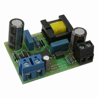
NCP1012GEVB
Description
EVAL BOARD FOR NCP1012G
Manufacturer
ON Semiconductor
Specifications of NCP1012GEVB
Design Resources
NCP1012 Eval Brd BOM NCP1012GEVB Gerber Files NCP1012 Eval Brd Schematic
Main Purpose
AC/DC, Primary Side
Outputs And Type
1, Isolated
Voltage - Output
12V
Voltage - Input
230VAC
Regulator Topology
Flyback
Frequency - Switching
100kHz
Board Type
Fully Populated
Utilized Ic / Part
NCP1012
Lead Free Status / RoHS Status
Lead free / RoHS Compliant
Current - Output
-
Power - Output
-
Lead Free Status / Rohs Status
Lead free / RoHS Compliant
For Use With/related Products
NCP1012G
Other names
NCP1012GEVBOS


A 7.0 W NCP1013- -based Flyback Converter
Featuring Low Standby Power
NCP1013- -65 kHz operating in a 7.0 W converter up to
70C of ambient temperature. We can increase the output
board implementing the diagram in Figure 30 and the
following results were achieved, with either the auxiliary
winding in place or through the Dynamic Self- -Supply:
Vin = 230 Vac, auxiliary winding, Pout = 0, Pin = 60 mW
Vin = 100 Vac, auxiliary winding, Pout = 0, Pin = 42 mW
Vin = 230 Vac, Dynamic Self- -Supply, Pout = 0,
Pin = 300 mW
Vin = 100 Vac, Dynamic Self- -Supply, Pout = 0,
Pin = 130 mW
Pout = 7.0 W, η = 81% @ 230 Vac, with auxiliary winding
Pout = 7.0 W, η = 81.3 @ 100 Vac, with auxiliary winding
Vbulk
47 mF/
450 V
Figure 30 depicts another typical application showing a
Measurements have been taken from a demonstration
C2
+
+ 100 mF/10 V
R2
3.3 k
C3
Figure 30. A Typical Converter Delivering 7.0 W from a Universal Mains
+ C10
33 mF/25 V
1N4148
D4
C9
1 nF
1
2
3
4
R4 22
NCP1013P06
V
NC
GND
FB
CC
Aux
T1
GND
GND
D
MUR160
8
7
5
http://onsemi.com
C8
10 nF
400 V
D3
20
R7
100 k/
1 W
power since an auxiliary winding is used, the DSS is
disabled, and thus offering more room for the MOSFET. In
this application, the feedback is made via a TLV431 whose
low bias current (100 mA min) helps to lower the no- -load
standby power.
the following transformers are available from Coilcraft:
A9619- -C, Lp = 3.0 mH, Np:Ns = 1:0.1, 7.0 W
application on universal mains, including auxiliary winding,
NCP1013- -65kHz.
A0032- -A, Lp = 6.0 mH, Np:Ns = 1:0.055, 10 W
application on European mains, DSS operation only,
NCP1013- -65 kHz.
Coilcraft
1102 Silver Lake Road
CARY IL 60013
Email: info@coilcraft.com
Tel.: 847- -639- -6400
Fax.: 847- -639- -1469
IC1
SFH6156--2
For a quick evaluation of Figure 30 application example,
Y1 Type
2.2 nF
C5
T1
D2
MBRS360T3
IC2
TLV431
R3
1 k
470 mF/16 V
C6 C8
100 nF
+
C4
+
22 mH
L2
R5
39 k
R6
4.3 k
+
100 mF/16 V
C7
12 V @
0.6 A
GND
Related parts for NCP1012GEVB
Image
Part Number
Description
Manufacturer
Datasheet
Request
R

Part Number:
Description:
Self−Supplied Monolithic Switcher for Low Standby−Power Offline SMPS
Manufacturer:
ONSEMI [ON Semiconductor]
Datasheet:

Part Number:
Description:
ON Semiconductor [VOLTAGE REGULATOR]
Manufacturer:
ON Semiconductor
Datasheet:
Part Number:
Description:
357-036-542-201 CARDEDGE 36POS DL .156 BLK LOPRO
Manufacturer:
ON Semiconductor
Datasheet:
Part Number:
Description:
357-036-542-201 CARDEDGE 36POS DL .156 BLK LOPRO
Manufacturer:
ON Semiconductor
Datasheet:
Part Number:
Description:
357-036-542-201 CARDEDGE 36POS DL .156 BLK LOPRO
Manufacturer:
ON Semiconductor
Datasheet:
Part Number:
Description:
357-036-542-201 CARDEDGE 36POS DL .156 BLK LOPRO
Manufacturer:
ON Semiconductor
Datasheet:
Part Number:
Description:
357-036-542-201 CARDEDGE 36POS DL .156 BLK LOPRO
Manufacturer:
ON Semiconductor
Datasheet:
Part Number:
Description:
357-036-542-201 CARDEDGE 36POS DL .156 BLK LOPRO
Manufacturer:
ON Semiconductor
Datasheet:
Part Number:
Description:
357-036-542-201 CARDEDGE 36POS DL .156 BLK LOPRO
Manufacturer:
ON Semiconductor
Datasheet:
Part Number:
Description:
357-036-542-201 CARDEDGE 36POS DL .156 BLK LOPRO
Manufacturer:
ON Semiconductor
Datasheet:
Part Number:
Description:
357-036-542-201 CARDEDGE 36POS DL .156 BLK LOPRO
Manufacturer:
ON Semiconductor
Datasheet:
Part Number:
Description:
357-036-542-201 CARDEDGE 36POS DL .156 BLK LOPRO
Manufacturer:
ON Semiconductor
Datasheet:
Part Number:
Description:
Manufacturer:
ON Semiconductor
Datasheet:
Part Number:
Description:
Manufacturer:
ON Semiconductor
Datasheet: