NCP1271ADAPGEVB ON Semiconductor, NCP1271ADAPGEVB Datasheet - Page 4
NCP1271ADAPGEVB
Manufacturer Part Number
NCP1271ADAPGEVB
Description
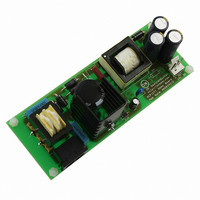
EVAL BOARD FOR NCP1271ADAPG
Manufacturer
ON Semiconductor
Datasheets
1.NCP1271P100G.pdf
(21 pages)
2.NCP1271ADAPGEVB.pdf
(1 pages)
3.NCP1271ADAPGEVB.pdf
(10 pages)
Specifications of NCP1271ADAPGEVB
Design Resources
NCP1271 Adapter EVB BOM NCP1271ADAPGEVB Gerber Files NCP1271EVB Schematic
Main Purpose
AC/DC, Primary Side
Outputs And Type
1, Isolated
Voltage - Output
19V
Current - Output
3A
Voltage - Input
85 ~ 265VAC
Regulator Topology
Flyback
Frequency - Switching
65kHz
Board Type
Fully Populated
Utilized Ic / Part
NCP1271
Silicon Manufacturer
On Semiconductor
Silicon Core Number
NCP1271
Kit Application Type
Power Management
Application Sub Type
PWM Controller
Peak Reflow Compatible (260 C)
No
Rohs Compliant
No
Lead Free Status / RoHS Status
Lead free / RoHS Compliant
Power - Output
-
Lead Free Status / Rohs Status
Lead free / RoHS Compliant
Other names
NCP1271ADAPGEVBOS


PIN FUNCTION DESCRIPTION
Pin No.
R
1
2
3
4
5
6
8
skip
R
R
Skip/ latch
CS
ramp
Skip/latch
Symbol
Gnd
V
Drv
CS
CS
HV
FB
FB
Gnd
CC
4
2
3
1
10V
V
V
FB
I
CS
Supply Voltage
Current Sense
10V
10V
Skip Adjust or
Driver Output
skip
High Voltage
4.8 V
IC Ground
Function
Feedback
1
Latchoff
16.7k
75.3k
V
FB
0
/ 3
180 ns
V
V
LEB
1 / 3
skip
skip
0
= R
= 1.2 V when pin 1 is opened
jittered ramp
current source
8 V
Figure 2. Functional Block Diagram
2.85 V
skip
A resistor to ground provides the adjustable standby skip level. Additionally, if this pin is
pulled higher than 8.0 V (typical), the controller latches off the drive.
An optocoupler collector pulls this pin low during regulation. If this voltage is less than
the Skip pin voltage, then the driver is pulled low and Soft−Skip mode is activated. If this
pin is open (>3 V) for more than 130 ms, then the controller is placed in a fault mode.
This pin senses the primary current for PWM regulation. The maximum primary current
is limited to 1.0 V / R
resistor R
for improved stability.
−
The NCP1271’s powerful output is capable of driving the gates of large Qg MOSFETs.
This is the positive supply of the device. The operating range is between 10 V (min) and
20 V (max) with a UVLO start threshold 12.6 V (typ).
This pin provides (1) Lossless startup sequence (2) Double hiccup fault mode (3)
Memory for latch−off shutdown and (4) Device protection if V
+
−
(1V max)
1
V
* I
+
−
V
PWM
skip
100uA
0
+
−
ss
TLD
http://onsemi.com
or
ramp
Soft start/ soft−skip
130ms
between the current sense node and this pin sets the compensation ramp
PWM
delay
7.5% Jittering
65, 100 kHz
Oscillator
+
−
management
4 ms/ 300 us
4
13 us filter
CS
disable
soft
skip
where R
V
V
&
skip
FB
CS
soft−skip
short
circuit
fault
is the current sense resistor. Additionally, a ramp
skip
+
−
soft
start
Description
S
R
OR
Q
Max duty
turn on internal bias
S
R
latch−off, reset
when Vcc < 4V
Counter
= 80%
4.1 mA when Vcc > 0.6 V
0.2 mA when Vcc < 0.6 V
double
hiccup
B2
Q
&
Q
S
R
turn off
CC
V
UVLO
CC
is shorted to GND.
+
+
−
−
9.1 V
driver:
+500 mA
/ −800 mA
20V
12.6/
5.8 V
6
5
8
V
Drv
HV
CC
Related parts for NCP1271ADAPGEVB
Image
Part Number
Description
Manufacturer
Datasheet
Request
R

Part Number:
Description:
ON Semiconductor [VOLTAGE REGULATOR]
Manufacturer:
ON Semiconductor
Datasheet:
Part Number:
Description:
357-036-542-201 CARDEDGE 36POS DL .156 BLK LOPRO
Manufacturer:
ON Semiconductor
Datasheet:
Part Number:
Description:
357-036-542-201 CARDEDGE 36POS DL .156 BLK LOPRO
Manufacturer:
ON Semiconductor
Datasheet:
Part Number:
Description:
357-036-542-201 CARDEDGE 36POS DL .156 BLK LOPRO
Manufacturer:
ON Semiconductor
Datasheet:
Part Number:
Description:
357-036-542-201 CARDEDGE 36POS DL .156 BLK LOPRO
Manufacturer:
ON Semiconductor
Datasheet:
Part Number:
Description:
357-036-542-201 CARDEDGE 36POS DL .156 BLK LOPRO
Manufacturer:
ON Semiconductor
Datasheet:
Part Number:
Description:
357-036-542-201 CARDEDGE 36POS DL .156 BLK LOPRO
Manufacturer:
ON Semiconductor
Datasheet:
Part Number:
Description:
357-036-542-201 CARDEDGE 36POS DL .156 BLK LOPRO
Manufacturer:
ON Semiconductor
Datasheet:
Part Number:
Description:
357-036-542-201 CARDEDGE 36POS DL .156 BLK LOPRO
Manufacturer:
ON Semiconductor
Datasheet:
Part Number:
Description:
357-036-542-201 CARDEDGE 36POS DL .156 BLK LOPRO
Manufacturer:
ON Semiconductor
Datasheet:
Part Number:
Description:
357-036-542-201 CARDEDGE 36POS DL .156 BLK LOPRO
Manufacturer:
ON Semiconductor
Datasheet:
Part Number:
Description:
Manufacturer:
ON Semiconductor
Datasheet:
Part Number:
Description:
Manufacturer:
ON Semiconductor
Datasheet:
Part Number:
Description:
Manufacturer:
ON Semiconductor
Datasheet: