MCP1630DM-DDBS1 Microchip Technology, MCP1630DM-DDBS1 Datasheet - Page 12
MCP1630DM-DDBS1
Manufacturer Part Number
MCP1630DM-DDBS1
Description
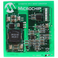
BOARD DEMO BOOST AUTO INPUT
Manufacturer
Microchip Technology
Type
DC/DC Switching Converters, Regulators & Controllersr
Specifications of MCP1630DM-DDBS1
Main Purpose
DC/DC, Step Up
Outputs And Type
1, Non-Isolated
Voltage - Output
36.5V
Current - Output
400mA
Voltage - Input
9 ~ 18V
Regulator Topology
Boost
Frequency - Switching
500kHz
Board Type
Fully Populated
Utilized Ic / Part
MCP1630
Silicon Manufacturer
Microchip
Silicon Core Number
MCP1630, PIC12F683
Core Architecture
PIC
Core Sub-architecture
PIC12
Silicon Family Name
Piccolo
Product
Power Management Modules
Lead Free Status / RoHS Status
Not applicable / Not applicable
Power - Output
-
Lead Free Status / Rohs Status
Lead free / RoHS Compliant
For Use With/related Products
MCP1630, PIC12F683
Lead Free Status / RoHS Status
Lead free / RoHS Compliant, Not applicable / Not applicable


MCP1630 Automotive Input Boost Converter Demo Board User’s Guide
2.3
DS51608B-page 8
GETTING STARTED
The MCP1630 Automotive Input Boost Converter Demo Board is fully assembled and
tested for automotive input. The board requires the use of an external input voltage
source (+9V to 18V) and external load.
2.3.1
2.3.1.1
1. Connect the positive side of the input source (+) to TP1.
2. Connect the negative or return side (-) of the input source to TP2. Refer to
FIGURE 2-1:
Input +
Input -
Figure 2-1. The input voltage source should be limited to the 0V to +18V range.
For normal operation, the input voltage should be between +9V to +18V. The
input voltage must not exceed an absolute maximum of +20V.
Power Input and Output Connection
POWERING THE MCP1630 AUTOMOTIVE INPUT BOOST CONVERTER
DEMO BOARD
Set-up Configuration Diagram.
Programming
Header
© 2007 Microchip Technology Inc.
Output +
Output -
Related parts for MCP1630DM-DDBS1
Image
Part Number
Description
Manufacturer
Datasheet
Request
R

Part Number:
Description:
BOARD CONV DEMO MCP1630 TRPL-OUT
Manufacturer:
Microchip Technology
Datasheet:

Part Number:
Description:
BOARD DEMO FOR MCP1630
Manufacturer:
Microchip Technology
Datasheet:

Part Number:
Description:
BOARD DEMO MCP1630 BIAS SUPPLY
Manufacturer:
Microchip Technology
Datasheet:

Part Number:
Description:
BOARD DEMO BOOST COUPLED INDUCTR
Manufacturer:
Microchip Technology
Datasheet:

Part Number:
Description:
BOARD DEM MCP1630 BOOST MODE LED
Manufacturer:
Microchip Technology
Datasheet:

Part Number:
Description:
Manufacturer:
Microchip Technology Inc.
Datasheet:
Part Number:
Description:
Manufacturer:
Microchip Technology Inc.
Datasheet:
Part Number:
Description:
Manufacturer:
Microchip Technology Inc.
Datasheet:
Part Number:
Description:
Manufacturer:
Microchip Technology Inc.
Datasheet:
Part Number:
Description:
Manufacturer:
Microchip Technology Inc.
Datasheet:
Part Number:
Description:
Manufacturer:
Microchip Technology Inc.
Datasheet: