DAK-71A Power Integrations, DAK-71A Datasheet
DAK-71A
Specifications of DAK-71A


Related parts for DAK-71A


DAK-71A Summary of contents
Page 1
... The products and applications illustrated herein (including circuits external to the products and transformer construction) may be covered by one or more U.S. and foreign patents or potentially by pending U.S. and foreign patent applications assigned to Power Integrations. A complete list of Power Integrations’ patents may be found at www.powerint.comT. ...
Page 2
... Although this board is designed to satisfy safety isolation requirements, the engineering prototype has not been agency approved. Therefore, all testing should be performed using an isolated source to provide power to the prototype board. Power Integrations Tel: +1 408 414 9200 Fax: +1 408 414 9201 www.powerint.com Table Of Contents ...
Page 3
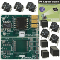
... This report contains the power supply specification, schematic, bill of materials, transformer documentation, printed circuit board layout, and performance data. Top Side Bottom Side Figure 1 - EP-71 Populated Circuit Board Photograph. Page EP-71 3 DC-DC Power Supply Power Integrations Tel: +1 408 414 9200 Fax: +1 408 414 9201 www.powerint.com ...
Page 4
... Output Voltage Output Ripple Voltage Continuous Output Current Peak Output Current Total Output Power Continuous Output Power Peak Output Power Efficiency Environmental Safety Isolation Ambient Temperature Power Integrations Tel: +1 408 414 9200 Fax: +1 408 414 9201 www.powerint.com Symbol Min Typ Max ...
Page 5
... Schematic *All resistors and capacitors 0805 size unless specified otherwise Page EP-71 3 DC-DC Power Supply Figure 2 - EP-71 Schematic. Tel: +1 408 414 9200 Fax: +1 408 414 9201 Power Integrations www.powerint.com ...
Page 6
... Section 10). 4.3 Output Rectification Schottky output diode D1 enables low loss rectification of the secondary winding voltage. Low ESR tantalum output capacitors C9, reduce switching ripple and minimize Power Integrations Tel: +1 408 414 9200 Fax: +1 408 414 9201 www.powerint.com 19-Jul-2005 Diode D2 ...
Page 7
... Capacitor C12 provides a soft-finish characteristic, preventing output voltage overshoot during startup of the converter. 5 PCB Layout Figure 3 - Top Side, SMT Printed Circuit Layout (Top View). Figure 4 - Bottom Side, SMT Printed Circuit Layout (Top View). Page EP-71 3 DC-DC Power Supply Power Integrations Tel: +1 408 414 9200 Fax: +1 408 414 9201 www.powerint.com ...
Page 8
... ERJ-6GEYJ750V ERJ-6GEYJ102V 1 kΩ ERJ-6ENF3402V 34.0 kΩ, 1% ERJ-6ENF2002V 20.0 kΩ, 1% ER14.5 Transformer LSTA30825 SIL6029 IM 040 202 31 150 V TVS SMAJ150A 19-Jul-2005 Manufacturer Power Integrations Sharp Catalyst Semiconductor UCC Panasonic AVX Panasonic Panasonic Kemet Panasonic Panasonic Panasonic Vishay generic Zierick Chilisin Chilisin ...
Page 9
... Pins 1-3, all other windings open Pins 1-3, with pins 6/7-9/10 shorted Description Tel: +1 408 414 9200 Fax: +1 408 414 9201 9,10 WDG #3 2T #28 AWG x2 6,7 4 WDG #2 8T #34 AWG 5 1500 VDC 120 µH, +/-10% 7.5 MHz (Min.) 3.0 µH (Max 312 nH/T LG Power Integrations www.powerint.com ...
Page 10
... Use one layer of item [5] for basic insulation. Outer Insulation Assemble and secure (glue or clamp, item [6]) core halves. Final Assembly Dip varnish item [7] and cure. Power Integrations Tel: +1 408 414 9200 Fax: +1 408 414 9201 www.powerint.com Figure 6 - Transformer Build Diagram. 19-Jul-2005 Tape ...
Page 11
... Transformer Spreadsheets Page EP-71 3 DC-DC Power Supply Power Integrations Tel: +1 408 414 9200 Fax: +1 408 414 9201 www.powerint.com ...
Page 12
... EP-71 3 DC-DC Power Supply Power Integrations Tel: +1 408 414 9200 Fax: +1 408 414 9201 www.powerint.com 19-Jul-2005 Page ...
Page 13
... Figure 7 - Efficiency vs. Output Load, Room Temperature. Page EP-71 3 DC-DC Power Supply VIN = 36 VDC VIN = 48 VDC VIN = 57 VDC VIN = 75 VDC 1.00 1.25 1.50 Load Current (A) Tel: +1 408 414 9200 Fax: +1 408 414 9201 1.75 2.00 Power Integrations www.powerint.com ...
Page 14
... Figure 8 9.2.2 Line 3.40 3.35 3.30 3.25 3.20 30 Figure 9 - Line Regulation, Room Temperature. Power Integrations Tel: +1 408 414 9200 Fax: +1 408 414 9201 www.powerint.com VIN = 36 VDC VIN = 48 VDC VIN = 57 VDC VIN = 36 VDC VIN = 48 VDC VIN = 57 VDC VIN = 75 VDC 0.5 ...
Page 15
... VDC, Full Load. Upper 0 div. DRAIN , µs / div. Lower: V DRAIN Page EP-71 3 DC-DC Power Supply Input Voltage (VDC) Figure 12 – 57 VDC, Full Load. Upper: I Lower: V Tel: +1 408 414 9200 Fax: +1 408 414 9201 div. DRAIN , µs / div. DRAIN Power Integrations www.powerint.com ...
Page 16
... Averaging minimizes the appearance of the 400 kHz switching ripple in the output voltage scope plot. The load current step was used to trigger the horizontal sweep of the oscilloscope. Power Integrations Tel: +1 408 414 9200 Fax: +1 408 414 9201 www.powerint.com Figure 14 - Start-up Profile, 57 VDC, No Load (Worst-case) ...
Page 17
... Lower: Output Voltage, 20 mV, 500 µs / div. Page EP-71 3 DC-DC Power Supply Figure 18 - Transient Response, 57 VDC, 75-100-75% Load Step. Upper: Load Current div. Lower: Output Voltage, 20 mV, 500 µs / div. Power Integrations Tel: +1 408 414 9200 Fax: +1 408 414 9201 www.powerint.com ...
Page 18
... Figure 19 - Oscilloscope Probe Prepared for Ripple Measurement (End Cap and Ground Lead Removed). Figure 20 - Oscilloscope Probe with Probe Master 5125BA BNC Adapter (Modified with Wires for Probe Ground for Ripple Measurement, and Two Parallel Decoupling Capacitors Added). Power Integrations Tel: +1 408 414 9200 Fax: +1 408 414 9201 www.powerint.com ...
Page 19
... EP-71 3 DC-DC Power Supply Figure 22 - Ripple, 48 VDC, Full Load. Upper: 50 µs / div div. Lower: 2 µs / div div. Figure 24 – Ripple, 75 VDC, Full Load. Upper: 50 µs / div div. Lower: 2 µs / div div. Power Integrations Tel: +1 408 414 9200 Fax: +1 408 414 9201 www.powerint.com ...
Page 20
... DPA423G case temperature of 79 °C. This is well below the recommended maximum case temperature of 100 °C. An infrared measurement taken at nominal-line (48 VDC) is provided. Ambient DPA423G (U1) Transformer core (T1) Output Rectifier (D1) Output Capacitor (C7) Power Integrations Tel: +1 408 414 9200 Fax: +1 408 414 9201 www.powerint.com ° Measured Temperature ( C) Item 36 VDC 48 VDC 57 VDC ...
Page 21
... Figure 25- Infrared Thermograph of Top of EP-71 Board, 48 VDC, Full Load, Room Ambient. Page EP-71 3 DC-DC Power Supply TOP VIEW BOTTOM VIEW Tel: +1 408 414 9200 Fax: +1 408 414 9201 Power Integrations www.powerint.com ...
Page 22
... Crossover Frequency = 10.0 kHz, Phase Margin = 60° Figure 27 - Gain-Phase Plot, 36 VDC, Light Load (100 mA). Vertical Scale: Gain = div, Phase = 30° / div. Crossover Frequency = 0.9 kHz, Phase Margin = 65° Power Integrations Tel: +1 408 414 9200 Fax: +1 408 414 9201 www.powerint.com 19-Jul-2005 Page ...
Page 23
... Vertical Scale: Gain = div, Phase = 30° / div. Crossover Frequency = 0.9 kHz, Phase Margin = 60° The results indicate adequate loop bandwidth and significant gain and phase margin. Page EP-71 3 DC-DC Power Supply Power Integrations Tel: +1 408 414 9200 Fax: +1 408 414 9201 www.powerint.com ...
Page 24
... Revision History Date Author 11-Mar-04 SH 16-Mar-04 PV 22-Mar-04 PV 02-Apr-04 KM 19-Jul-05 PV Power Integrations Tel: +1 408 414 9200 Fax: +1 408 414 9201 www.powerint.com Revision Description & changes 0.1 First draft 0.2 Minor text edits 1.0 Insert board photograph 1.1 Added vendor name to Bill of Materials 1 ...
Page 25
... Page EP-71 3 DC-DC Power Supply Notes Power Integrations Tel: +1 408 414 9200 Fax: +1 408 414 9201 www.powerint.com ...
Page 26
... EP-71 3 DC-DC Power Supply Power Integrations Tel: +1 408 414 9200 Fax: +1 408 414 9201 www.powerint.com Notes 19-Jul-2005 Page ...
Page 27
... Page EP-71 3 DC-DC Power Supply Notes Power Integrations Tel: +1 408 414 9200 Fax: +1 408 414 9201 www.powerint.com ...
Page 28
... EP-71 3 DC-DC Power Supply For the latest updates, visit our website: www.powerint.com Power Integrations reserves the right to make changes to its products at any time to improve reliability or manufacturability. Power Integrations does not assume any liability arising from the use of any device or circuit described herein. POWER INTEGRATIONS ...