IRDC3812 International Rectifier, IRDC3812 Datasheet
IRDC3812
Specifications of IRDC3812


Related parts for IRDC3812

IRDC3812 Summary of contents
Page 1
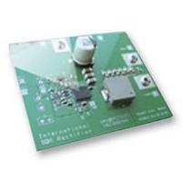
... This user guide contains the schematic and bill of materials for the IR3812 evaluation board. The guide describes operation and use of the evaluation board itself. Detailed information for IR3812 is available in the IR3812 data sheet. :0.6V p IRDC3812 MOSFET for optimum cost application and 1 ...
Page 2
... Ground of V Vcc+ Optional Vcc input Vcc- Ground for optional Vcc input VOUT- Ground of V VOUT+ V (+1.8V) out Vp_Ext Optional Tracking input Agnd Analog (Signal) Ground IRDC3812 Vcc input cannot be connected unless R15 is The value of R17 and R28 can be in out 2 ...
Page 3
... Connection Diagram Vp_Ext V CC+ GROUND Agnd Fig. 1: Connection diagram of IR3812 evaluation board Rev 0.1 01/07/2008 V = +12v GROUND in IRDC3812 GROUND V OUT 3 ...
Page 4
... Fig. 3: Board layout, bottom overlay (rear view) Rev 0.1 01/07/2008 Fig. 2: Board layout, top overlay IRDC3812 4 ...
Page 5
... AGND Plain Single point connection between AGND and PGND. Rev 0.1 01/07/2008 Fig. 4: Board layout, mid-layer I Fig. 5: Board layout, mid-layer II IRDC3812 PGND Plain 5 ...
Page 6
... Rev 0.1 01/07/2008 1 AGnd3 15 Hg Vref Vcc IRDC3812 ...
Page 7
... Thick film, 1/10W, 1% 0603 600kHz, 4A, SupIRBuck 5x6mm Module Banana Jack, Insulated - Solder Terminal, Black Banana Jack- Insulated - Solder Terminal, Red Banana Jack- Insulated - Solder Terminal, Green IRDC3812 Manufacturer Mfr. Part Number Panasonic ECJ-3YX1C106K Panasonic ECJ-1VB1H104K Panasonic ECJ-1VB1C103K Murata GRM1885C1H181JA01 Murata GRM1885C1H220JA01 Panasonic ECJ-1VB1C105K ...
Page 8
... Vin=Vcc=12.0V, Vp=0- 0.6V, Vo=0.75V, Io=0- 4A, Room Temperature, No Air Flow Fig. 7: Start Load Fig. 9: Pre-Bias Start up, 0A Load Fig. 11: Inductor node at 4A load :LX Rev 0.1 01/07/2008 : 0- 0. out 4 ss :0. out :0. out IRDC3812 Fig. 8: Tracking Operation 0. Load out Fig. 10: Output Voltage Ripple, 4A load, V :0.6V out , 4 Fig. 12: Short (Hiccup) Recovery out : out :0. ...
Page 9
... TYPICAL OPERATING WAVEFORMS Vin=Vcc=12V, Vo=0.75V, Io=2A- 4A, Room Temperature, No Air Flow Rev 0.1 01/07/2008 Fig. 13: Transient Response step out 4 out IRDC3812 9 ...
Page 10
... TYPICAL OPERATING WAVEFORMS Vin=Vcc=12V, Vo=0.75V, Io=4A, Room Temperature, No Air Flow Fig. 14: Bode Plot at 4A load shows a bandwidth of 40kHz and phase margin of 48 degrees Rev 0.1 01/07/2008 IRDC3812 10 ...
Page 11
... Efficiency Vcc=Vin=12V 1.4 1.2 1.0 0.8 0.6 0.4 0.2 0 Power Loss Vcc=Vin=12V Rev 0.1 01/07/2008 1.5 2.5 Load Current (A) Efficiency Vin=12V@ Vcc=5V Fig.15: Efficiency versus load current 1 2 Load Current (A) Power Loss Vin=12V @ Vcc=5V Fig.16: Power loss versus load current IRDC3812 3 ...
Page 12
... THERMAL IMAGES Vin=Vcc=12V, Vo=0.75V, Io=4A, Room Temperature, No Air Flow Rev 0.1 01/07/2008 Fig. 17: Thermal Image at 4A load Test point 1 is the IR3812 IRDC3812 12 ...
Page 13
... The pad lands (the 4 big pads other than the 11 IC pins) length and width should be equal to maximum part pad length and width. However, the minimum metal to metal spacing should be no less than 0.17mm for 2 oz. Copper; no less than 0.1mm for 1 oz. Copper and no less than 0.23mm for 3 oz. Copper. Rev 0.1 01/07/2008 IRDC3812 ...
Page 14
... Ensure that the solder resist in between the lead lands and the pad land is ≥ 0.15mm due to the high aspect ratio of the solder resist strip separating the lead lands from the pad land. Rev 0.1 01/07/2008 IRDC3812 ...
Page 15
... The maximum length and width of the land pad stencil aperture should be equal to the solder resist opening minus an annular 0.2mm pull back to decrease the incidence of shorting the center land to the lead lands when the part is pushed into the solder paste. Rev 0.1 01/07/2008 IRDC3812 ...
Page 16
... This product has been designed and qualified for the Consumer market. Rev 0.1 01/07/2008 233 Kansas St., El Segundo, California 90245, USA Tel: (310) 252-7105 Visit us at www.irf.com for sales contact information Data and specifications subject to change without notice. 11/07 IRDC3812 TAC Fax: (310) 252-7903 ...