LM3407EVAL National Semiconductor, LM3407EVAL Datasheet - Page 11
LM3407EVAL
Manufacturer Part Number
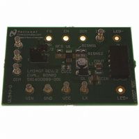
LM3407EVAL
Description
BOARD EVALUATION FOR LM3407
Manufacturer
National Semiconductor
Series
PowerWise®r
Specifications of LM3407EVAL
Current - Output / Channel
350mA
Outputs And Type
1, Non-Isolated
Voltage - Output
4.5V
Features
Dimmable
Voltage - Input
4.5 ~ 30V
Utilized Ic / Part
LM3407
Lead Free Status / RoHS Status
Contains lead / RoHS non-compliant


EN pin is internally pulled high by a 5µA current source. Con-
necting the EN pin to ground will force the device to enter low
power shutdown mode. To resume normal operation, leave
the EN pin open or drive with a logic high voltage.
INPUT UNDER-VOLTAGE LOCK-OUT (UVLO)
The LM3407 incorporates an input Under-Voltage Lock-Out
(UVLO) circuit with hysteresis to keep the device disabled
when the input voltage (V
threshold, 3.4V typical. During the device power-up, internal
circuits are held inactive and the UVLO comparator monitors
the voltage level at the VIN pin continuously. When the VIN
pin voltage exceeds the UVLO threshold, 3.6V typical, the in-
ternal circuits are then enabled and normal operation begins.
Application Information
SWITCHING FREQUENCY SELECTION
The selection of switching frequency is based on the consid-
eration of the conversion efficiency, size of the passive com-
ponents, and the total solution cost. In general, increasing the
switching frequency will allow the use of smaller external
components but will decrease the conversion efficiency.
Thus, the selection of switching frequency is a compromise
between the system requirements and may vary from design
to design. The LM3407 switching frequency can be set in the
range from 300 kHz to 1 MHz by adjusting the value of R
The switching frequency is inversely proportional to the value
of R
sistor with 1% tolerance between 40 kΩ and 96 kΩ and with
good thermal stability is suggested.
The switching frequency is estimated by the expression be-
low:
In the equation, f
frequency setting resistance. The above equation is only valid
for oscillator frequencies in the range of 300 kHz to 1 MHz,
so the frequency setting resistance will be in the range of
about 40 kΩ to 150 kΩ.
LED CURRENT SETTING
The LED current setting is important to the lifetime, reliability,
and color temperature of the LED string. The LED current
should be properly selected according to the characteristics
of the LED used. Over-driving the LED array can cause the
color temperature to shift and will shorten the lifetime of the
LEDs. The output current of the LM3407 can be set by
R
To ensure the accuracy of the output current, a resistor with
1% tolerance should be used for R
the designer to ensure that the rated power of the resistor is
not exceeded with reasonable margin. For example, when
I
steady state is (0.35A)
dicating a resistor of 1/8W power rating is appropriate.
OUT
ISNS
FS
is set to 350 mA, the total power dissipation on R
, which is calculated from the following equation:
. In order to guarantee good operation stability, a re-
SW
is the oscillator frequency and R
2
x 0.565Ω, which equals 69 mW, in-
IN
) falls below the Lock-Out Low
ISNS
. It is also important for
FS
ISNS
is the
FS
in
.
11
INPUT AND OUTPUT CAPACITORS
The input capacitor supplies instantaneous current to the
LM3407 converter when the internal power switch Q1 turns
ON. The input capacitor filters the noise and transient voltage
from the input power source. Using low ESR capacitors such
as ceramic and tantalum capacitors is recommended. Similar
to the selection criteria for the output capacitor, ceramic ca-
pacitors are the best choice for the input to the LM3407 due
to their high ripple current rating, low ESR, and relatively small
size compared to other types. A 4.7 µF X7R ceramic capacitor
for the input capacitor is recommended
The output capacitor C
ple, filter noise, and smooth output voltage. This capacitor
should have low ESR and adequate capacitance. Excessively
large output capacitances create long enable and disable
times, which is particularly significant when a high dimming
frequency is used. Since the loading and input conditions dif-
fer from design to design, a 2.2 µF X7R ceramic capacitor is
a good initial selection. A DC voltage rating equal to or higher
than twice the forward voltage of the LED string is recom-
mended.
C
small brightness variation is acceptable. Omitting C
helps reduce the cost and board size of the converter. With
the absence of C
ductor current. In order to ensure proper operation of the
converter the peak inductor current must not exceed the rated
forward current of the LEDs. Otherwise the LEDs may be
damaged.
SELECTION OF INDUCTOR
In order to achieve accurate constant current output, the
LM3407 is required to operate in Continuous Conduction
Mode (CCM) under all operating conditions. In general, the
magnitude of the inductor ripple current should be kept as
small as possible. If the PCB size is not limited, higher induc-
tance values result in better accuracy of the output current.
However, in order to minimize the physical size of the circuit,
an inductor with minimum physical outline should be selected
such that the converter always operates in CCM and the peak
inductor current does not exceed the saturation current limit
of the inductor. The ripple and peak current of the inductor
can be calculated as follows:
Inductor Peak to Peak Ripple Current:
Peak Inductor Current:
where n is the number of LEDs in a string and V
voltage of one LED.
The minimum inductance required for the specific application
can be calculated by:
OUT
is optional and can be omitted for applications where
OUT
, the LED forward current equals the in-
OUT
is used to reduce LED current rip-
F
is the forward
www.national.com
OUT
also
Related parts for LM3407EVAL
Image
Part Number
Description
Manufacturer
Datasheet
Request
R

Part Number:
Description:
Precision Fahrenheit Temperature Sensors
Manufacturer:
National Semiconductor
Part Number:
Description:
National Semiconductor [8-Bit D/A Converter]
Manufacturer:
National Semiconductor
Datasheet:
Part Number:
Description:
National Semiconductor [Media Coprocessor]
Manufacturer:
National Semiconductor
Datasheet:
Part Number:
Description:
Digitally Controlled Tone and Volume Circuit with Stereo Audio Power Amplifier, Microphone Preamp Stage and National 3D Sound
Manufacturer:
National Semiconductor
Datasheet:
Part Number:
Description:
Digitally Controlled Tone and Volume Circuit with Stereo Audio Power Amplifier, Microphone Preamp Stage and National 3D Sound
Manufacturer:
National Semiconductor
Datasheet:
Part Number:
Description:
AC97 Rev 2 Codec with Sample Rate Conversion and National 3D Sound
Manufacturer:
National Semiconductor
Part Number:
Description:
Manufacturer:
National Semiconductor
Datasheet:
Part Number:
Description:
Manufacturer:
National Semiconductor
Datasheet:
Part Number:
Description:
General Purpose, Low Voltage, Low Power, Rail-to-Rail Output Operational Amplifiers
Manufacturer:
National Semiconductor
Datasheet:
Part Number:
Description:
8-bit 20 MSPS flash A/D converter.
Manufacturer:
National Semiconductor
Datasheet:
Part Number:
Description:
Low Noise Quad Operational Amplifier
Manufacturer:
National Semiconductor
Datasheet:
Part Number:
Description:
Quad Differential Line Receivers
Manufacturer:
National Semiconductor
Datasheet:
Part Number:
Description:
Quad High Speed Trapezoidal? Bus Transceiver
Manufacturer:
National Semiconductor
Datasheet:
Part Number:
Description:
Dual Line Receiver
Manufacturer:
National Semiconductor
Datasheet: