LM3445-208277EV/NOPB National Semiconductor, LM3445-208277EV/NOPB Datasheet - Page 8
LM3445-208277EV/NOPB
Manufacturer Part Number
LM3445-208277EV/NOPB
Description
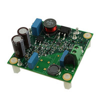
BOARD EVAL LED DRIVER LM3445
Manufacturer
National Semiconductor
Series
PowerWise®r
Specifications of LM3445-208277EV/NOPB
Current - Output / Channel
500mA
Outputs And Type
1, Non-Isolated
Features
Dimmable with Standard TRIAC Dimmer, Power Factor Correction
Voltage - Input
176 ~ 305 VAC
Utilized Ic / Part
LM3445
Lead Free Status / RoHS Status
Lead free / RoHS Compliant
Voltage - Output
-
Other names
LM3445-208277EV
Available stocks
Company
Part Number
Manufacturer
Quantity
Price
Company:

Part Number:
LM3445-208277EV/NOPB
Manufacturer:
National Semiconductor
Quantity:
135


www.national.com
Application Information
FUNCTIONAL DESCRIPTION
The LM3445 contains all the necessary circuitry to build a line-
powered (mains powered) constant current LED driver whose
output current can be controlled with a conventional triac dim-
mer.
OVERVIEW OF PHASE CONTROL DIMMING
A basic "phase controlled" triac dimmer circuit is shown in
Figure 2.
An RC network consisting of R1, R2, and C1 delay the turn
on of the triac until the voltage on C1 reaches the trigger volt-
age of the diac. Increasing the resistance of the potentiometer
(wiper moving downward) increases the turn-on delay which
decreases the on-time or "conduction angle" of the triac (θ).
This reduces the average power delivered to the load. Voltage
waveforms for a simple triac dimmer are shown in Figure 3.
Figure 3a shows the full sinusoid of the input voltage. Even
when set to full brightness, few dimmers will provide 100%
on-time, i.e., the full sinusoid.
FIGURE 2. Basic Triac Dimmer
30060312
8
Figure 3b shows a theoretical waveform from a dimmer. The
on-time is often referred to as the "conduction angle" and may
be stated in degrees or radians. The off-time represents the
delay caused by the RC circuit feeding the triac. The off-time
be referred to as the "firing angle" and is simply 180° - θ.
Figure 3c shows a waveform from a so-called reverse phase
dimmer, sometimes referred to as an electronic dimmer.
These typically are more expensive, microcontroller based
dimmers that use switching elements other than triacs. Note
that the conduction starts from the zero-crossing, and termi-
nates some time later. This method of control reduces the
noise spike at the transition.
Since the LM3445 has been designed to assess the relative
on-time and control the LED current accordingly, most phase-
control dimmers, both forward and reverse phase, may be
used with success.
FIGURE 3. Line Voltage and Dimming Waveforms
30060313
Related parts for LM3445-208277EV/NOPB
Image
Part Number
Description
Manufacturer
Datasheet
Request
R

Part Number:
Description:
National Semiconductor [8-Bit D/A Converter]
Manufacturer:
National Semiconductor
Datasheet:
Part Number:
Description:
National Semiconductor [Media Coprocessor]
Manufacturer:
National Semiconductor
Datasheet:
Part Number:
Description:
Digitally Controlled Tone and Volume Circuit with Stereo Audio Power Amplifier, Microphone Preamp Stage and National 3D Sound
Manufacturer:
National Semiconductor
Datasheet:
Part Number:
Description:
Digitally Controlled Tone and Volume Circuit with Stereo Audio Power Amplifier, Microphone Preamp Stage and National 3D Sound
Manufacturer:
National Semiconductor
Datasheet:
Part Number:
Description:
AC97 Rev 2 Codec with Sample Rate Conversion and National 3D Sound
Manufacturer:
National Semiconductor
Part Number:
Description:
Manufacturer:
National Semiconductor
Datasheet:
Part Number:
Description:
Manufacturer:
National Semiconductor
Datasheet:
Part Number:
Description:
General Purpose, Low Voltage, Low Power, Rail-to-Rail Output Operational Amplifiers
Manufacturer:
National Semiconductor
Datasheet:
Part Number:
Description:
8-bit 20 MSPS flash A/D converter.
Manufacturer:
National Semiconductor
Datasheet:
Part Number:
Description:
Low Noise Quad Operational Amplifier
Manufacturer:
National Semiconductor
Datasheet:
Part Number:
Description:
Quad Differential Line Receivers
Manufacturer:
National Semiconductor
Datasheet:
Part Number:
Description:
Quad High Speed Trapezoidal? Bus Transceiver
Manufacturer:
National Semiconductor
Datasheet:
Part Number:
Description:
Dual Line Receiver
Manufacturer:
National Semiconductor
Datasheet:
Part Number:
Description:
TTL to 10k ECL Level Translator with Latch
Manufacturer:
National Semiconductor
Datasheet: