LM3429BSTEVAL/NOPB National Semiconductor, LM3429BSTEVAL/NOPB Datasheet - Page 2
LM3429BSTEVAL/NOPB
Manufacturer Part Number
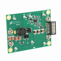
LM3429BSTEVAL/NOPB
Description
BOARD EVAL FOR BOOST LM3429
Manufacturer
National Semiconductor
Series
PowerWise®r
Specifications of LM3429BSTEVAL/NOPB
Current - Output / Channel
1A
Outputs And Type
1, Non-Isolated
Features
Dimmable
Voltage - Input
10 ~ 26 V
Utilized Ic / Part
LM3429
Core Chip
LM3429
Topology
Buck-Boost
No. Of Outputs
1
Dimming Control Type
PWM / Analog
Development Tool Type
Hardware - Eval/Demo Board
Mcu Supported Families
LM3429 Family
Msl
MSL 1 - Unlimited
Lead Free Status / RoHS Status
Lead free by exemption / RoHS compliant by exemption
Voltage - Output
-
Other names
*LM3429BSTEVAL
*LM3429BSTEVAL/NOPB
LM3429BSTEVAL
*LM3429BSTEVAL/NOPB
LM3429BSTEVAL
Available stocks
Company
Part Number
Manufacturer
Quantity
Price
Company:

Part Number:
LM3429BSTEVAL/NOPB
Manufacturer:
National Semiconductor
Quantity:
135


www.national.com
DAP
Pin Descriptions
(15)
Pin
10
11
12
13
14
1
2
3
4
5
6
7
8
9
COMP
AGND
PGND
Name
GATE
nDIM
CSH
OVP
HSN
RCT
HSP
DAP
V
NC
V
IS
CC
IN
High-Side LED Current Sense
High-Side LED Current Sense
Thermal pad on bottom of IC
Main Switch Current Sense
Resistor Capacitor Timing
Internal Regulator Output
Over-Voltage Protection
Current Sense High
Gate Drive Output
Analog Ground
No Connection
Compensation
Power Ground
Not DIM input
Input Voltage
Description
Negative
Positive
Bypass with 100 nF capacitor to AGND as close to the device as possible in
the circuit board layout.
Connect a capacitor to AGND.
Connect a resistor to AGND to set the signal current. For analog dimming,
connect a controlled current source or a potentiometer to AGND as detailed in
the Analog Dimming section.
Connect a resistor from the switch node and a capacitor to AGND to set the
switching frequency.
Connect to PGND through the DAP copper circuit board pad to provide proper
ground return for CSH, COMP, and RCT.
Connect to a resistor divider from V
(OVLO). Turn-off threshold is 1.24V and hysteresis for turn-on is provided by
20 µA current source.
Connect a PWM signal for dimming as detailed in the PWM Dimming section
and/or a resistor divider from V
(UVLO). Turn-on threshold is 1.24V and hysteresis for turn-off is provided by
20 µA current source.
Leave open.
Connect to AGND through the DAP copper circuit board pad to provide proper
ground return for GATE.
Connect to the gate of the external NFET.
Bypass with a 2.2 µF–3.3 µF, ceramic capacitor to PGND.
Connect to the drain of the main N-channel MosFET switch for R
or to a sense resistor installed in the source of the same device.
Connect through a series resistor to the positive side of the LED current sense
resistor.
Connect through a series resistor to the negative side of the LED current sense
resistor.
Star ground, connecting AGND and PGND.
2
Application Information
IN
to program input under-voltage lockout
O
to program output over-voltage lockout
DS-ON
sensing
Related parts for LM3429BSTEVAL/NOPB
Image
Part Number
Description
Manufacturer
Datasheet
Request
R

Part Number:
Description:
National Semiconductor [8-Bit D/A Converter]
Manufacturer:
National Semiconductor
Datasheet:
Part Number:
Description:
National Semiconductor [Media Coprocessor]
Manufacturer:
National Semiconductor
Datasheet:
Part Number:
Description:
Digitally Controlled Tone and Volume Circuit with Stereo Audio Power Amplifier, Microphone Preamp Stage and National 3D Sound
Manufacturer:
National Semiconductor
Datasheet:
Part Number:
Description:
Digitally Controlled Tone and Volume Circuit with Stereo Audio Power Amplifier, Microphone Preamp Stage and National 3D Sound
Manufacturer:
National Semiconductor
Datasheet:
Part Number:
Description:
AC97 Rev 2 Codec with Sample Rate Conversion and National 3D Sound
Manufacturer:
National Semiconductor
Part Number:
Description:
Manufacturer:
National Semiconductor
Datasheet:
Part Number:
Description:
Manufacturer:
National Semiconductor
Datasheet:
Part Number:
Description:
General Purpose, Low Voltage, Low Power, Rail-to-Rail Output Operational Amplifiers
Manufacturer:
National Semiconductor
Datasheet:
Part Number:
Description:
8-bit 20 MSPS flash A/D converter.
Manufacturer:
National Semiconductor
Datasheet:
Part Number:
Description:
Low Noise Quad Operational Amplifier
Manufacturer:
National Semiconductor
Datasheet:
Part Number:
Description:
Quad Differential Line Receivers
Manufacturer:
National Semiconductor
Datasheet:
Part Number:
Description:
Quad High Speed Trapezoidal? Bus Transceiver
Manufacturer:
National Semiconductor
Datasheet:
Part Number:
Description:
Dual Line Receiver
Manufacturer:
National Semiconductor
Datasheet:
Part Number:
Description:
TTL to 10k ECL Level Translator with Latch
Manufacturer:
National Semiconductor
Datasheet: