LM3503ITL-25EV National Semiconductor, LM3503ITL-25EV Datasheet - Page 16
LM3503ITL-25EV
Manufacturer Part Number
LM3503ITL-25EV
Description
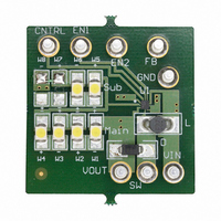
BOARD EVALUATION LM3503ITL-25
Manufacturer
National Semiconductor
Series
PowerWise®r
Specifications of LM3503ITL-25EV
Current - Output / Channel
9mA
Outputs And Type
2, Non-Isolated
Voltage - Output
25 V
Features
Dual Display(s)
Voltage - Input
2.7 ~ 5.5V
Utilized Ic / Part
LM3503
Core Chip
LM3503
Topology
Boost
No. Of Outputs
1
Output Voltage
25V
Input Voltage
2.5V To 5.5V
Development Tool Type
Hardware - Eval/Demo Board
Lead Free Status / RoHS Status
Not applicable / Not applicable


www.national.com
Application Information
V
V
Eff:
Fs:
I
L:
D:
∆i
I
For CCM operation, the duty cycle can be computed with:
D:
V
V
For DCM operation, the duty cycle can be computed with:
D:
V
V
I
Fs:
L:
INDUCTOR SELECTION
In order to maintain inductance, an inductor used with the
LM3503 should have a saturation current rating larger than
the peak inductor current of the particular application. Induc-
tors with low DCR values contribute decreased power losses
and increased efficiency. The peak inductor current can be
computed for both modes of operation: CCM and DCM.
The cycle-by-cycle peak inductor current for CCM operation
can be computed with:
OUT
L
OUT
IN
OUT
(avg): Average Inductor Current.
OUT
IN
OUT
IN
L
:
:
:
:
:
: White LED Current/Load Current.
:
: Output Voltage.
: Output Voltage.
Duty Cycle for CCM Operation.
Input Voltage.
Duty Cycle for DCM Operation.
Input Voltage.
Switching Frequency.
Inductor Value/Inductance Magnitude.
Input Voltage.
Output Voltage.
Efficiency of the LM3503.
Switching Frequency.
White LED Current/Load Current.
Inductance Magnitude/Inductor Value.
Duty Cycle for CCM operation.
Inductor Ripple Current.
(Continued)
16
V
Eff:
Fs:
I
L:
D:
I
∆i
I
The cycle-by-cycle peak inductor current for DCM operation
can be computed with:
V
Fs:
L:
D:
I
The minimum inductance magnitude/inductor value for the
LM3503 can be calculated using the following, which is only
valid when the duty cycle is
D:
D’:
R
Fs:
V
L:
This equation gives the value required to prevent subhar-
monic oscillations. The result of this equation and the induc-
tor ripple currents should be accounted for when choosing
an inductor value.
Some recommended Inductor manufactures included but
are not limited to:
CAPACITOR SELECTION
Multilayer ceramic capacitors are the best choice for use
with the LM3503. Multilayer ceramic capacitors have the
lowest equivalent series resistance (ESR). Applied voltage
or DC bias, temperature, dielectric material type (X7R, X5R,
Y5V, etc), and manufacturer component tolerance have an
affect on the true or effective capacitance of a ceramic
capacitor. Be aware of how your application will affect a
particular ceramic capacitor by analyzing the aforemen-
tioned factors of your application. Before selecting a capaci-
tor always consult the capacitor manufacturer’s data curves
to verify the effective or true capacitance of the capacitor in
your application.
OUT
PEAK
L
PEAK
Coilcraft
IN
IN
IN
(avg): Average Inductor Current.
DS(ON)
L
:
:
:
:
:
:
: Peak Inductor Current.
Input Voltage.
Switching Frequency.
Inductance Magnitude/Inductor Value.
Duty Cycle for DCM Operation.
: NMOS Power Switch ON Resistance.
Input Voltage.
Efficiency of the LM3503.
Switching Frequency.
White LED Current/Load Current.
Inductance Magnitude/Inductor Value.
Duty Cycle for CCM Operation.
Peak Inductor Current.
Inductor Ripple Current.
Duty Cycle.
1-D.
Switching Frequency.
Input Voltage.
Inductance Magnitude/Inductor Value.
DO1608C-223
DT1608C-223
www.coilcraft.com
>
0.5:
Related parts for LM3503ITL-25EV
Image
Part Number
Description
Manufacturer
Datasheet
Request
R

Part Number:
Description:
IC LED DRVR WHT BCKLT 10MICROSMD
Manufacturer:
National Semiconductor
Datasheet:
Part Number:
Description:
IC LED DRVR WHT BCKLT 10MICROSMD
Manufacturer:
National Semiconductor
Datasheet:
Part Number:
Description:
IC LED DRVR WHT BCKLT 10MICROSMD
Manufacturer:
National Semiconductor
Datasheet:
Part Number:
Description:
IC LED DRVR WHT BCKLT 10MICROSMD
Manufacturer:
National Semiconductor
Datasheet:

Part Number:
Description:
IC, LED DRIVER, CONSTANT CURRENT, µSMD16
Manufacturer:
National Semiconductor
Datasheet:

Part Number:
Description:
Dual-Display Constant Current LED Driver with Analog Brightness Control
Manufacturer:
National Semiconductor
Datasheet:
Part Number:
Description:
LM3503 Dual-Display Constant Current LED Driver with Analog Brightness Control; Package: MICRO SMD; No of Pins: 10; Qty per Container: 250; Container: Reel
Manufacturer:
National Semiconductor
Datasheet:
Part Number:
Description:
National Semiconductor [8-Bit D/A Converter]
Manufacturer:
National Semiconductor
Datasheet:
Part Number:
Description:
National Semiconductor [Media Coprocessor]
Manufacturer:
National Semiconductor
Datasheet:
Part Number:
Description:
Digitally Controlled Tone and Volume Circuit with Stereo Audio Power Amplifier, Microphone Preamp Stage and National 3D Sound
Manufacturer:
National Semiconductor
Datasheet:
Part Number:
Description:
Digitally Controlled Tone and Volume Circuit with Stereo Audio Power Amplifier, Microphone Preamp Stage and National 3D Sound
Manufacturer:
National Semiconductor
Datasheet:
Part Number:
Description:
AC97 Rev 2 Codec with Sample Rate Conversion and National 3D Sound
Manufacturer:
National Semiconductor
Part Number:
Description:
Manufacturer:
National Semiconductor
Datasheet:
Part Number:
Description:
Manufacturer:
National Semiconductor
Datasheet: