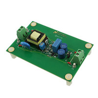
LM3445-120VFLBK/NOPB National Semiconductor, LM3445-120VFLBK/NOPB Datasheet - Page 16

LM3445-120VFLBK/NOPB
Manufacturer Part Number
LM3445-120VFLBK/NOPB
Description
PROGRAMMERS, DEVELOPMENT SYSTEMS
Manufacturer
National Semiconductor
Series
PowerWise®r
Specifications of LM3445-120VFLBK/NOPB
Current - Output / Channel
365mA
Outputs And Type
1, Isolated
Voltage - Output
20V
Features
Dimmable, TRIAC Dimmable
Voltage - Input
90 ~ 135VAC
Utilized Ic / Part
LM3445
Lead Free Status / RoHS Status
Lead free / RoHS Compliant
www.national.com
Circuit Analysis and Explanations
INJECTING LINE VOLTAGE INTO FILTER-2 (achieving
PFC > 0.95)
If a small portion (750mV to 1.00V) of line voltage is injected
at FLTR2 of the LM3445, the circuit is essentially turned into
a constant power flyback as shown in Figure 6.
The LM3445 works as a constant off-time controller normally,
but by injecting the 1.0V rectified AC voltage into the FLTR2
FIGURE 6. Line Voltage Injection Circuit
FIGURE 8. Typical Operation of FLTR2 Pin
30115217
16
pin, the on-time can be made to be constant. With a DCM
Flyback, Δi needs to increase as the input voltage line in-
creases. Therefore a constant on-time (since inductor L is
constant) can be obtained.
By using the line voltage injection technique, the FLTR2 pin
has the voltage wave shape shown in Figure 7 on it with no
triac dimmer in-line. Voltage at V
below 1.25V. At 1.25V current limit is tripped. C11 is small
enough not to distort the AC signal but adds a little filtering.
Although the on-time is probably never truly constant, it can
be observed in Figure 8 how (by adding the rectified voltage)
the on-time is adjusted.
For this evaluation board, the following resistor values are
used:
R2 = R7 = 309kΩ
R15 = 3.48kΩ
Therefore the voltages observed on the FLTR2 pin will be as
follows for listed input voltages:
For VIN = 90V
For VIN = 120V
For VIN = 135V
Using this technique, a power factor greater than 0.95 can be
achieved without additional passive active power factor con-
trol (PFC) circuitry.
FIGURE 7. FLTR2 Waveform with No Dimmer
RMS
RMS
RMS
, V
, V
, V
FLTR2
FLTR2
FLTR2
= 0.71V
= 0.95V
= 1.07V
FLTR2
peak should be kept
30115218
30115216


