© 2010 National Semiconductor Corporation
LM3433 10A to 40A LED
Driver Evaluation Board
Introduction
The LM3433 is an adaptive constant on-time DC/DC buck
constant current controller designed to drive a high brightness
LED (HB LED) at high forward currents. It is a true current
source that provides a constant current with constant ripple
current regardless of the LED forward voltage drop. The
board can accept an input voltage ranging from -9V to -14V
w.r.t. GND. The output configuration allows the anodes of
multiple LEDs to be tied directly to the ground referenced
chassis for maximum heat sink efficacy when a negative input
voltage is used.
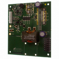
LM3433 High Current Board
Description
The evaluation board is designed to provide a constant cur-
rent in the range of 10A to 60A (although the board is ther-
mally limited to approximately 40A continuous operation) and
can connect directly to a Luminus Devices, Inc. PhlatLight
PT-120 or similar high current LED. It is ideal for pulsing an
LED at 30A or greater for applications such as rear and for-
ward projection. The LM3433 requires two input voltages for
operation. A positive voltage with respect to GND is required
for the bias and control circuitry and a negative voltage with
respect to GND is required for the main power input. This al-
lows for the capability of using common anode LEDs so that
the anodes can be tied to the ground referenced chassis. The
evaluation board only requires one input voltage of -12V with
respect to GND (any high current 12V supply will work). The
positive voltage w.r.t. GND on the board is supplied by the
LM5002 circuit (see below). Initially the output current is set
at the minimum of approximately 10A with the POT P1 fully
counter-clockwise. To set the desired current level a short
may be connected between LED+ and LED-, then use a cur-
rent probe and turn the POT clockwise until the desired
current is reached. PWM dimming FETs are included on-
board for testing when the LED can be connected directly next
to the board. A shutdown test post on J2, ENA, is included so
that startup and shutdown functions can be tested using an
external voltage. Note that the test points for GND and -12V
are for measurement only, the high current input source
should be connected through J1.
LM5002 Circuit
The positive voltage w.r.t. GND on the board is supplied by
the LM5002 circuit. The LM5002 feedback is level shifted so
that the output that supplies the LM3433 bias circuitry will re-
main at +5V w.r.t. GND regardless of where VEE is in the -9V
to -14V range. The LM5002 circuit also provides a UVLO
function to remove the possibility of the LM3433 drawing high
currents at input voltages less than -9V during startup. This
circuit was designed with enough output current to power a
small 5V sideblower fan (Sunon part number B0502AFB2-8)
to help keep the inductor, and therefore the board to some
degree, cooler if extreme ambient temperatures are expect-
ed. One LM5002 circuit can supply enough current to drive
PhlatLight® is a registered trademark of Luminus Devices, Inc.
300894
®
National Semiconductor
Application Note 1937
Clinton Jensen
January 14, 2010
the positive voltage for multiple LM3433 circuits in a system,
up to approximately 100.
Setting the LED Current
The LM3433 evaluation board is designed so that the LED
current can be set in multiple ways. There is a shunt on J2
initially connecting the ADJ pin to the POT allowing the current
to be adjusted using the POT P1. This POT will apply a volt-
age to the ADJ pin between 0.3V and 1.5V w.r.t. GND to
adjust the voltage across the sense resistor (R
The shunt may also be removed and an external voltage pos-
itive w.r.t. GND can then be applied to the ADJ test point on
the board. A 2mΩ resistor comes mounted on the board (five
10mΩ resistors in parallel) so using the V
in the Typical Performance Characteristics section the current
can be set using the following equation:
Alternatively the shunt can be removed and the ADJ test point
can be connected to the VINX test point to fix V
for 30A output current.
PWM Dimming
The LM3433 is capable of high speed PWM dimming in ex-
cess of 40kHz. Dimming is accomplished by shorting across
the LED with a FET(s). Dimming FETs are included on the
evaluation board for testing LEDs placed close to the board.
The FETs on the evaluation board should be removed if using
dimming FETs remotely placed close to the LED (STRONG-
LY recommended). If the FETs cannot be placed directly next
to the LED then some form of snubber may be required to
prevent damage to the LM3433, LM5111, and LM2937 due
to the large spikes caused by inductance between the LED
and FETs. D4, C17, and R32 may be used to populate a
snubber circuit.
To use the dimming function apply square wave to the PWM
test point on the board that has a positive voltage w.r.t. GND.
When this pin is pulled high the dimming FET is enabled and
the LED turns off. When it is pulled low the dimming FET is
turned off and the LED turns on. A scope plot of PWM dim-
ming is included in the Typical Performance Characteristics
section showing 120Hz dimming at 20% duty cycle.
Reducing Component Count
This board has been optimized to reduce losses in the power
FETs and dimming FETs by using the LM5111 gate drivers
to increase the gate drive current as well as the gate voltage
for minimum R
efficiency can be tolerated when PWM dimming then some
components may be removed. As shipped an LM5111 is used
to drive the PWM FET gates. The LM5111 is powered by us-
ing D6 and C25 to form a charge pump to generate a positive
voltage above GND that is approximately equal to |VEE|. This
voltage is then regulated down to 12V above LED- with the
LM2937 to power the LM5111. The result is high gate drive
current capability and a high gate voltage for the dimming
FETs. With the use of the LM5111s on the main power FETs
DS(ON)
I
LED
. If more power dissipation and/or lower
= V
SENSE
/R
SENSE
SENSE
SENSE
vs. V
www.national.com
SENSE
ADJ
at 60mV
) R15.
graph