NCP1351LEDGEVB ON Semiconductor, NCP1351LEDGEVB Datasheet - Page 2
NCP1351LEDGEVB
Manufacturer Part Number
NCP1351LEDGEVB
Description
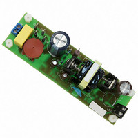
EVAL BOARD FOR NCP1351LEDG
Manufacturer
ON Semiconductor
Datasheets
1.NCP1351APG.pdf
(27 pages)
2.NCP1351LEDGEVB.pdf
(11 pages)
3.NCP1351LEDGEVB.pdf
(3 pages)
Specifications of NCP1351LEDGEVB
Design Resources
NCP1351 EVB BOM NCP1351LEDGEVB Gerber Files NCP1351LED EVB Schematic
Current - Output / Channel
700mA
Outputs And Type
1, Isolated
Voltage - Output
33V
Features
Short-Circuit Protection
Voltage - Input
85 ~ 265 V
Utilized Ic / Part
NCP1351
Core Chip
NCP1351
Topology
Flyback
No. Of Outputs
1
Output Current
700mA
Output Voltage
33V
Development Tool Type
Hardware - Eval/Demo Board
Leaded Process Compatible
Yes
Rohs Compliant
Yes
Lead Free Status / RoHS Status
Lead free / RoHS Compliant
For Use With/related Products
NCP1351LEDG
Other names
NCP1351LEDGEVBOS


Setup Procedure:
current to the demo board can be measured. The oscilloscope should be set up so that the output
ripple can be monitored.
Test Procedure:
2/5/2009
Set the equipment as shown in the diagram on the next page so that the output voltage and
Vadj
AC Source
1. Switch the electronic load on, set to constant resistance mode and the load adjust to zero
2. With the AC source OFF, set the current limit on the AC source to 1 A and the output
3. Turn on the AC source and the power supply demo board output voltage should be the
4. Adjust the electronic load from no load slowly up to the rated output current. The output
5. Reduce the AC input to 90 Vac and make sure the conditions of test 4 above still hold.
6. Return the input to 115 Vac and continue to increase the load slowly and the current
7. Set the electronic load to back to zero and the output voltage should return to the rated
8. Check the AC input power. It should be below 400 mW.
load; switch all of the digital meters on (assuming they are wired properly for voltage and
current sensing); turn the oscilloscope on with sensing in AC mode and 200 mV per
division vertical and a sweep rate of 5 uS per division. Connect the scope probe to the
demo board’s output terminals.
voltage to 115 Vac.
rated output voltage 34 +1 volt/- 1 volts on the DVM.
voltage should remain within 700 +/- 50mA. The output ripple on the oscilloscope should
be less than 500 mV peak-to-peak.
should remain constant within 700 +/- 50mA as voltage collapses (constant current
output.)
level.
(Required if not
in AC source)
Iadj
WATTS
115 Vac
AC out
AC in
Board Under Test
DC out
- 2 -
-
+
DVM
amps
volts
DVM
-
-
+
+
O'scope
Electronic
www.onsemi.com
Load
-
Adj
Related parts for NCP1351LEDGEVB
Image
Part Number
Description
Manufacturer
Datasheet
Request
R

Part Number:
Description:
ON Semiconductor [VOLTAGE REGULATOR]
Manufacturer:
ON Semiconductor
Datasheet:
Part Number:
Description:
357-036-542-201 CARDEDGE 36POS DL .156 BLK LOPRO
Manufacturer:
ON Semiconductor
Datasheet:
Part Number:
Description:
357-036-542-201 CARDEDGE 36POS DL .156 BLK LOPRO
Manufacturer:
ON Semiconductor
Datasheet:
Part Number:
Description:
357-036-542-201 CARDEDGE 36POS DL .156 BLK LOPRO
Manufacturer:
ON Semiconductor
Datasheet:
Part Number:
Description:
357-036-542-201 CARDEDGE 36POS DL .156 BLK LOPRO
Manufacturer:
ON Semiconductor
Datasheet:
Part Number:
Description:
357-036-542-201 CARDEDGE 36POS DL .156 BLK LOPRO
Manufacturer:
ON Semiconductor
Datasheet:
Part Number:
Description:
357-036-542-201 CARDEDGE 36POS DL .156 BLK LOPRO
Manufacturer:
ON Semiconductor
Datasheet:
Part Number:
Description:
357-036-542-201 CARDEDGE 36POS DL .156 BLK LOPRO
Manufacturer:
ON Semiconductor
Datasheet:
Part Number:
Description:
357-036-542-201 CARDEDGE 36POS DL .156 BLK LOPRO
Manufacturer:
ON Semiconductor
Datasheet:
Part Number:
Description:
357-036-542-201 CARDEDGE 36POS DL .156 BLK LOPRO
Manufacturer:
ON Semiconductor
Datasheet:
Part Number:
Description:
357-036-542-201 CARDEDGE 36POS DL .156 BLK LOPRO
Manufacturer:
ON Semiconductor
Datasheet:
Part Number:
Description:
Manufacturer:
ON Semiconductor
Datasheet:
Part Number:
Description:
Manufacturer:
ON Semiconductor
Datasheet:
Part Number:
Description:
Manufacturer:
ON Semiconductor
Datasheet: