LM3405XEVAL National Semiconductor, LM3405XEVAL Datasheet - Page 11
LM3405XEVAL
Manufacturer Part Number
LM3405XEVAL
Description
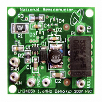
BOARD EVALUATION LM3405X
Manufacturer
National Semiconductor
Series
PowerWise®r
Specifications of LM3405XEVAL
Current - Output / Channel
1A
Outputs And Type
1, Non-Isolated
Voltage - Output
0.2 ~ 13.5 V
Features
Dimmable
Voltage - Input
3 ~ 15V
Utilized Ic / Part
LM3405
Kit Contents
Board, Datasheet
Svhc
No SVHC (15-Dec-2010)
Kit Features
Cycle-by-Cycle Current Limit,
Rohs Compliant
No
Lead Free Status / RoHS Status
Contains lead / RoHS non-compliant


capacitor will have high ESL and a 0805 ceramic chip capac-
itor will have very low ESL. At the operating frequency of the
LM3405, certain capacitors may have an ESL so large that
the resulting inductive impedance (2πfL) will be higher than
that required to provide stable operation. It is strongly recom-
mended to use ceramic capacitors due to their low ESR and
low ESL. A 10µF multilayer ceramic capacitor (MLCC) is a
good choice for most applications. In cases where large ca-
pacitance is required, use surface mount capacitors such as
Tantalum capacitors and place at least a 1µF ceramic capac-
itor close to the V
X7R or X5R dielectrics. Consult capacitor manufacturer
datasheet to see how rated capacitance varies over operating
conditions.
OUTPUT CAPACITOR (C2)
The output capacitor is selected based upon the desired re-
duction in LED current ripple. A 1µF ceramic capacitor results
in very low LED current ripple for most applications. Due to
the high switching frequency, the 1µF capacitor alone (without
feed-forward capacitor C4) can filter more than 90% of the
inductor current ripple for most applications where the sum of
LED dynamic resistance and R1 is larger than 1Ω. Since the
internal compensation is tailored for small output capacitance
with very low ESR, it is strongly recommended to use a ce-
ramic capacitor with capacitance less than 3.3µF.
Given the availability and quality of MLCCs and the expected
output voltage of designs using the LM3405, there is really no
need to review other capacitor technologies. A benefit of ce-
ramic capacitors is their ability to bypass high frequency
noise. A certain amount of switching edge noise will couple
through the parasitic capacitances in the inductor to the out-
put. A ceramic capacitor will bypass this noise. In cases where
large capacitance is required, use Electrolytic or Tantalum
capacitors with large ESR, and verify the loop performance
on bench. Like the input capacitor, recommended multilayer
ceramic capacitors are X7R or X5R. Again, verify actual ca-
pacitance at the desired operating voltage and temperature.
Check the RMS current rating of the capacitor. The maximum
RMS current rating of the capacitor is:
One may select a 1206 size ceramic capacitor for C2, since
its current rating is typically higher than 1A, more than enough
for the requirement.
FEED-FORWARD CAPACITOR (C4)
The feed-forward capacitor (designated as C4) connected in
parallel with the LED string is required to provide multiple
benefits to the LED driver design. It greatly improves the large
signal transient response and suppresses LED current over-
shoot that may otherwise occur during PWM dimming; it also
helps to shape the rise and fall times of the LED current pulse
during PWM dimming thus reducing EMI emission; it reduces
LED current ripple by bypassing some of inductor ripple from
flowing through the LED. For most applications, a 1µF ce-
ramic capacitor is sufficient. In fact, the combination of a 1µF
feed-forward ceramic capacitor and a 1µF output ceramic ca-
pacitor leads to less than 1% current ripple flowing through
the LED. Lower and higher C4 values can be used, but bench
validation is required to ensure the performance meets the
application requirement.
Figure 13 shows a typical LED current waveform during PWM
dimming without feed-forward capacitor. At the beginning of
IN
pin. For MLCCs it is recommended to use
11
each PWM cycle, overshoot can be seen in the LED current.
Adding a 1µF feed-forward capacitor can totally remove the
overshoot as shown in Figure 14.
CATCH DIODE (D1)
The catch diode (D1) conducts during the switch off-time. A
Schottky diode is required for its fast switching time and low
forward voltage drop. The catch diode should be chosen such
that its current rating is greater than:
The reverse breakdown rating of the diode must be at least
the maximum input voltage plus appropriate margin. To im-
prove efficiency, choose a Schottky diode with a low forward
voltage drop.
BOOST DIODE (D2)
A standard diode such as the 1N4148 type is recommended.
For V
small-signal Schottky diode is recommended for better effi-
ciency. A good choice is the BAT54 small signal diode.
FIGURE 14. PWM Dimming with a 1µF Feed-Forward
FIGURE 13. PWM Dimming without Feed-Forward
BOOST
circuits derived from voltages less than 3.3V, a
I
D1
Capacitor
Capacitor
= I
F
x (1-D)
20178969
20178970
www.national.com
Related parts for LM3405XEVAL
Image
Part Number
Description
Manufacturer
Datasheet
Request
R

Part Number:
Description:
Precision Fahrenheit Temperature Sensors
Manufacturer:
National Semiconductor
Part Number:
Description:
National Semiconductor [8-Bit D/A Converter]
Manufacturer:
National Semiconductor
Datasheet:
Part Number:
Description:
National Semiconductor [Media Coprocessor]
Manufacturer:
National Semiconductor
Datasheet:
Part Number:
Description:
Digitally Controlled Tone and Volume Circuit with Stereo Audio Power Amplifier, Microphone Preamp Stage and National 3D Sound
Manufacturer:
National Semiconductor
Datasheet:
Part Number:
Description:
Digitally Controlled Tone and Volume Circuit with Stereo Audio Power Amplifier, Microphone Preamp Stage and National 3D Sound
Manufacturer:
National Semiconductor
Datasheet:
Part Number:
Description:
AC97 Rev 2 Codec with Sample Rate Conversion and National 3D Sound
Manufacturer:
National Semiconductor
Part Number:
Description:
Manufacturer:
National Semiconductor
Datasheet:
Part Number:
Description:
Manufacturer:
National Semiconductor
Datasheet:
Part Number:
Description:
General Purpose, Low Voltage, Low Power, Rail-to-Rail Output Operational Amplifiers
Manufacturer:
National Semiconductor
Datasheet:
Part Number:
Description:
8-bit 20 MSPS flash A/D converter.
Manufacturer:
National Semiconductor
Datasheet:
Part Number:
Description:
Low Noise Quad Operational Amplifier
Manufacturer:
National Semiconductor
Datasheet:
Part Number:
Description:
Quad Differential Line Receivers
Manufacturer:
National Semiconductor
Datasheet:
Part Number:
Description:
Quad High Speed Trapezoidal? Bus Transceiver
Manufacturer:
National Semiconductor
Datasheet: