LM2796TLEV National Semiconductor, LM2796TLEV Datasheet - Page 3
LM2796TLEV
Manufacturer Part Number
LM2796TLEV
Description
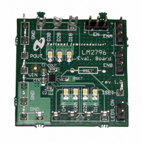
BOARD EVALUATION LM2796TL
Manufacturer
National Semiconductor
Series
PowerWise®r
Specifications of LM2796TLEV
Current - Output / Channel
20mA
Outputs And Type
7, Non-Isolated
Voltage - Output
4 V
Features
Charge Pump
Voltage - Input
2.7 ~ 5.5V
Utilized Ic / Part
LM2796
Lead Free Status / RoHS Status
Not applicable / Not applicable


Board Operation
BASIC CONNECTIONS
To operate the LM2796 evaluation board, connect a supply
voltage (2.7V-5.5V) between board connectors VIN and
GND.
Default Jumper Connections:
When these connections are all made correctly, all LEDs will
be ON.
R
The resistance of the R
currents of the LM2796 according to the following equation:
The default R
a DC output current of 15mA (typ.).
Component Rset’ is an optional leaded resistor replacement
for the surface mount Rset, provided for ease of use.
EN, ENA, AND ENB HEADERS: LED ACTIVATION AND
PWM BRIGHTNESS CONTROL
The header strips EN, ENA, and ENB can be used to enable/
disable the LM2796 and/or the LED (output) currents. The
connections to the ENx pins provided by these posts can
also be used to connect pulse-width modulated (PWM) sig-
nals to the LM2796 in order to adjust the average brightness
of the LEDs.
On each of these header strips, the post labeled “+” is
connected to VIN. The post labeled “-“ is connected to GND.
The middle post connects to EN, ENA, and ENB, respec-
tively.
Jumpers can be used to connect each ENx pin to either VIN
or GND. Connecting EN to VIN enables the charge pump
•
• ENA: Connects the “+” post to the middle post of the ENA
•
•
SET
header strip. This connects VIN to the EN pin of the
LM2796, enabling the part.
header strip. This connects VIN to the ENA pin of the
LM2796, enabling D1A-D4A outputs
ENB header strip. This connects VIN to the ENB pin of
the LM2796, enabling D1B-D3B outputs.
S_ON header strip. This connects the cathodes of all 7
LEDs to GND, establishing the LED current path.
EN: Connects the “+” post to the middle post of the EN
LEDS_ON: Jumper connects the two posts of the LED-
ENB: Connects the “+” post to the middle post of the
: SETTING LED CURRENTS
SET
I
Dxx
on the evaluation board is 8.3kΩ and gives
= 100 X (1.25V / Rset)
SET
resistor sets the DC output
3
and other internal circuitry of the LM2796. Connecting EN to
GND places the part in Shutdown mode.
When the part in enabled (EN = VIN), connecting ENA to VIN
enables the D1A-D4A LEDs. Connecting ENA to GND dis-
ables these LEDs. Similarly, connecting ENB to VIN enables
the D1B-D3B LEDs, and connecting ENB to GND disables
them.
A pulse signal (PWM) can be connected to the ENA and/or
ENB pins to adjust the brightness of the respective LED
banks. The duty cycle of the pulse signal determines the net
brightness, as perceived by the human eye. For example,
with a duty cycle of 50%, the LEDs will only be ON for 50%
of the time, and the perceived brightness will be approxi-
mately half of what the brightness is when the output current
flows continuously through the LEDs. Recommended fre-
quency range for PWM signals: 100Hz to 1kHz.
It is recommended that ENA and ENB pins be used for PWM
brightness adjustment (dimming). Toggling the voltage on
these pins turns the internal LM2796 current sources on and
off, and the charge pump stays ON continuously. Placing a
PWM signal on the EN pin repeatedly turns the internal
charge pump ON and OFF. Each time the charge pump is
activated, significant inrush current can be expected as the
large external capacitors are quickly recharged. This could
inject noise on the input line.
USING THE LEDS ON HEADERS TO MEASURE
OUTPUT CURRENTS OR TO DRIVE DIFFERENT LEDS
By removing the LEDS_ON jumper, LM2796 output currents
can easily be measured. Removing the jumper disconnects
the cathodes of all LEDs from GND, breaking the LED
current paths. By placing a current meter between the two
header pins, as shown on the following page in Figure 3, the
sum total of all LED currents can be measured.
With the LEDS_ON jumper removed, the current of an indi-
vidual output can be measured by placing a current meter
between a Dxx header and GND, as shown in Figure 4.
With such a connection, the voltage on pin Dxx will be almost
0V because the series resistance of the current meter is
likely to be quite small. Since the regulated output currents of
the LM2796 are almost completely independent of Dxx pin
voltage (provided V
this measurement will still be quite accurate.
With the LEDS_ON jumper removed, the LM2796 can drive
external LEDs simply by connecting each LED between a
Dxx output and GND. The LEDs on the evaluation board
need not be removed for this type of test/evaluation.
Dxx
is not too high to inhibit regulation),
www.national.com
Related parts for LM2796TLEV
Image
Part Number
Description
Manufacturer
Datasheet
Request
R

Part Number:
Description:
Accurate, 120 C-150 C Factory Preset Thermostat Lm27 Form
Manufacturer:
National Semiconductor Corporation
Datasheet:

Part Number:
Description:
Factory Preset Thermostat
Manufacturer:
National Semiconductor
Datasheet:
Part Number:
Description:
National Semiconductor [8-Bit D/A Converter]
Manufacturer:
National Semiconductor
Datasheet:
Part Number:
Description:
National Semiconductor [Media Coprocessor]
Manufacturer:
National Semiconductor
Datasheet:
Part Number:
Description:
Digitally Controlled Tone and Volume Circuit with Stereo Audio Power Amplifier, Microphone Preamp Stage and National 3D Sound
Manufacturer:
National Semiconductor
Datasheet:
Part Number:
Description:
Digitally Controlled Tone and Volume Circuit with Stereo Audio Power Amplifier, Microphone Preamp Stage and National 3D Sound
Manufacturer:
National Semiconductor
Datasheet:
Part Number:
Description:
AC97 Rev 2 Codec with Sample Rate Conversion and National 3D Sound
Manufacturer:
National Semiconductor
Part Number:
Description:
Manufacturer:
National Semiconductor
Datasheet:
Part Number:
Description:
Manufacturer:
National Semiconductor
Datasheet:
Part Number:
Description:
General Purpose, Low Voltage, Low Power, Rail-to-Rail Output Operational Amplifiers
Manufacturer:
National Semiconductor
Datasheet:
Part Number:
Description:
8-bit 20 MSPS flash A/D converter.
Manufacturer:
National Semiconductor
Datasheet:
Part Number:
Description:
Low Noise Quad Operational Amplifier
Manufacturer:
National Semiconductor
Datasheet:
Part Number:
Description:
Quad Differential Line Receivers
Manufacturer:
National Semiconductor
Datasheet:
Part Number:
Description:
Quad High Speed Trapezoidal? Bus Transceiver
Manufacturer:
National Semiconductor
Datasheet: