LM2794EVAL National Semiconductor, LM2794EVAL Datasheet - Page 11
LM2794EVAL
Manufacturer Part Number
LM2794EVAL
Description
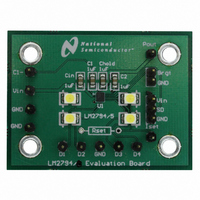
BOARD EVALUATION LM2794
Manufacturer
National Semiconductor
Specifications of LM2794EVAL
Current - Output / Channel
80mA
Outputs And Type
4, Non-Isolated
Voltage - Output
4 V
Features
Charge Pump
Voltage - Input
2.7 ~ 5.5V
Utilized Ic / Part
LM2794
Lead Free Status / RoHS Status
Not applicable / Not applicable


Application Information
I
The following procedures illustrate how to set and adjust
output current levels. For constant brightness or analog
brightness control, go to “Brightness control using BRGT”.
Otherwise refer to “Brightness control using PWM”.
Brightness Control Using PWM
1. Set the BRGT pin to 0V.
2. Determine the maximum desired I
3. Brightness control can be implemented by pulsing a
Brightness Control Using BRGT
1. Choose the maximum I
2. Use Table 3 to determine the value of R
3. Use Table 4 as a reference for the dimming profile of the
LED
BRGT
I
use Table 3 to select a value for R
equals 0V.
signal at the SD pin. LED brightness is proportional to
the duty cycle (D) of the PWM signal. For linear bright-
ness control over the full duty cycle adjustment range,
the PWM frequency (f) should be limited to accommo-
date the turn-on time (T
If the PWM frequency is much less than 100Hz, flicker
may be seen in the LEDs. For the LM2794, zero duty
cycle will turn off the LEDs and a 50% duty cycle will
result in an average I
LED current. For example, if R
15mA, a 50% duty cycle will result in an average I
7.5mA. For the LM2795 however, 100% duty cycle will
turn off the LEDs and a 50% duty cycle will result in an
average I
max voltage to be applied to the BRGT pin. For constant
brightness, set BRGT to a fixed voltage between 0V to
3V.
use the I
LEDs, when BRGT ranges from 0V to 3V.
0.0V
0.5V
1.0V
1.5V
2.0V
LED
CURRENT SELECTION PROCEDURES
equation to calculate R
LED
LED
1.15KΩ
1.54KΩ
1.91KΩ
374Ω
768Ω
5mA
equation above to calculate R
being half the programmed LED current.
TABLE 3. R
f
MAX
D x (1/f)
= D
LED
10mA
187Ω
383Ω
576Ω
768Ω
953Ω
ON
LED
LED Current
MIN
being half of the programmed
SET
>
SET
= 100µs) of the device.
desired and determine the
÷ T
T
Values
ON
by setting BRGT to 0V or
ON
SET
15mA
124Ω
255Ω
383Ω
624Ω
511Ω
LED
is set to program
(Continued)
SET
current. Use the
SET
when BRGT
SET
required or
20mA
93.1Ω
191Ω
287Ω
383Ω
475Ω
.
LED
of
11
CHARGE PUMP OUTPUT (P
The LM2794/5 charge pump is an unregulated switched
capacitor converter with a gain of 1.5. The voltage at the
output of the pump (the P
rail can be used to deliver additional current to other circuitry.
Figure 2 shows how to connect additional LEDs to P
ballast resistor sets the current through each LED, and LED
current matching is dependent on the LED forward voltage
matching. Because of this, LEDs driven by P
mended for functions where brightness matching is not criti-
cal, such as keypad backlighting.
Since P
usually practical only with a fixed input voltage. If the input
voltage is not fixed (Li-Ion battery, for example), using a
linear regulator between the P
recommended. National Semiconductor’s LP3985-4.5V low-
dropout linear regulator is a good choice for such an appli-
cation.
The voltage at P
supplied to the LM2794/5, the total LM2794/5 output current,
and the output resistance (R
pump. Output resistance is a model of the switching losses
of the charge pump. Resistances of the internal charge
pump switches (MOS transistors) are a primary component
of the LM2794/5 output resistance. Typical LM2794/5 output
resistance is 3.0Ω. For worst-case design calculations, using
an output resistance of 3.5Ω is recommended. (Worst-case
recommendation accounts for parameter shifts from part-to-
part variation and applies over the full operating temperature
range).
R
SET
BRGT
BRGT
2.5V
3.0V
0.0V
0.5V
1.0V
1.5V
2.0V
2.5V
3.0V
values are rounded off to the nearest 1% standard values.
OUT
is unregulated, driving LEDs directly off P
2.32KΩ
2.67KΩ
2.67KΩ
0.7mA
1.4mA
2.1mA
2.9mA
3.6mA
4.3mA
5.0mA
5mA
TABLE 4. LED Current
OUT
is dependent on the input voltage
OUT
1.33KΩ
10.1mA
1.15KΩ
1.33KΩ
1.4mA
2.9mA
4.3mA
5.8mA
7.2mA
8.7mA
10mA
LED Current
R
pin) is nominally 1.5 x V
OUT
OUT
SET
OUT
) of the LM2794/5 charge
)
Values
10.5mA
12.7mA
14.8mA
pin and the LEDs is
2.1mA
4.2mA
6.3mA
8.4mA
15mA
768Ω
909Ω
909Ω
OUT
www.national.com
are recom-
11.5mA
14.4mA
17.3mA
20.2mA
2.8mA
5.7mA
8.6mA
20mA
576Ω
665Ω
665Ω
IN
OUT
OUT
. This
. A
is
Related parts for LM2794EVAL
Image
Part Number
Description
Manufacturer
Datasheet
Request
R

Part Number:
Description:
Accurate, 120 C-150 C Factory Preset Thermostat Lm27 Form
Manufacturer:
National Semiconductor Corporation
Datasheet:

Part Number:
Description:
Factory Preset Thermostat
Manufacturer:
National Semiconductor
Datasheet:
Part Number:
Description:
National Semiconductor [8-Bit D/A Converter]
Manufacturer:
National Semiconductor
Datasheet:
Part Number:
Description:
National Semiconductor [Media Coprocessor]
Manufacturer:
National Semiconductor
Datasheet:
Part Number:
Description:
Digitally Controlled Tone and Volume Circuit with Stereo Audio Power Amplifier, Microphone Preamp Stage and National 3D Sound
Manufacturer:
National Semiconductor
Datasheet:
Part Number:
Description:
Digitally Controlled Tone and Volume Circuit with Stereo Audio Power Amplifier, Microphone Preamp Stage and National 3D Sound
Manufacturer:
National Semiconductor
Datasheet:
Part Number:
Description:
AC97 Rev 2 Codec with Sample Rate Conversion and National 3D Sound
Manufacturer:
National Semiconductor
Part Number:
Description:
Manufacturer:
National Semiconductor
Datasheet:
Part Number:
Description:
Manufacturer:
National Semiconductor
Datasheet:
Part Number:
Description:
General Purpose, Low Voltage, Low Power, Rail-to-Rail Output Operational Amplifiers
Manufacturer:
National Semiconductor
Datasheet:
Part Number:
Description:
8-bit 20 MSPS flash A/D converter.
Manufacturer:
National Semiconductor
Datasheet:
Part Number:
Description:
Low Noise Quad Operational Amplifier
Manufacturer:
National Semiconductor
Datasheet:
Part Number:
Description:
Quad Differential Line Receivers
Manufacturer:
National Semiconductor
Datasheet:
Part Number:
Description:
Quad High Speed Trapezoidal? Bus Transceiver
Manufacturer:
National Semiconductor
Datasheet: