LP5526TLEV National Semiconductor, LP5526TLEV Datasheet - Page 4
LP5526TLEV
Manufacturer Part Number
LP5526TLEV
Description
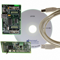
BOARD EVAL LP5526 LMU LED DRIVER
Manufacturer
National Semiconductor
Series
PowerWise®r
Specifications of LP5526TLEV
Current - Output / Channel
150mA
Outputs And Type
2 (25mA), 1 (150mA)
Voltage - Output
20 V
Features
Camera Flash, Dimmable, RGB Controller
Voltage - Input
3 ~ 5.5V
Utilized Ic / Part
LP5526
Lead Free Status / RoHS Status
Not applicable / Not applicable


www.national.com
GPIO TAB
BACKLIGHT TAB
HISTORY TAB
Figure 6. Backlight Tab
Figure 7. History Tab
Figure 5. GPIO Tab
20198204
20198205
20198206
4
In this tab it is possible to control GPIO bits and configure USB
board for reading/writing. Port A, B and L refer to USB inter-
face boards ports. Direction of the LP5526 GPIO pins can be
set with 'oenx' controls. With the 'datax' controls it is possible
to set the state of the GPIO pins, when they are set as output
(oenx = 1 / pressed down). When the GPIO pins are set as
input, these 'datax' buttons work as an indicator, and you can
read the state of the pins with the read-button.
With the USB interface I/O section it is possible to set/read
the GPIO pins state.
It is possible to configure port A of USB board as output or
input. If you want to use LP5526’s GPIO0…2 as output, you
have to configure port A as input.
It is important that ‘en_pwm_pin’ bit is set and GPIO0 (in USB
interface I/O) is set as output, if you want to use GPIO0 as
PWM input for any purpose (RGB, WLED or FLASH trigger-
ing).
In this tab the backlight LEDs can be controlled. Main and Sub
outputs can be enabled individually. If you select Large dis-
play mode, all LEDs are controlled by the main WLEDs con-
trols (also fading).
Current setting for the outputs are done with the sliders. You
can move the slides with arrow keys for more precise control,
or write values directly. Pressing ‘Write’ button writes adjusted
values to registers.
You can enable fade function by setting ‘Automatic fade en-
abled’. When new current value is set, the WLED currents will
automatically fade smoothly to new value. You can select
which LEDs fade effects. When ‘Large’ display mode is on,
set ‘Fade control switch’ to Main WLEDs to enable fading of
all WLEDs.
‘Fade execution time’ refers to the time to execute full range
current change in WLEDs.
External PWM control can be enabled to both Main and Sub
individually. External PWM input pin is GPIO[0].
The History Tab records the command sequence of your ses-
sion. I
dress and last is the data in hex format. You can copy-paste
this information to another application.
2
C address is on square brackets [], then register ad-
Related parts for LP5526TLEV
Image
Part Number
Description
Manufacturer
Datasheet
Request
R

Part Number:
Description:
National Semiconductor [8-Bit D/A Converter]
Manufacturer:
National Semiconductor
Datasheet:
Part Number:
Description:
National Semiconductor [Media Coprocessor]
Manufacturer:
National Semiconductor
Datasheet:
Part Number:
Description:
Digitally Controlled Tone and Volume Circuit with Stereo Audio Power Amplifier, Microphone Preamp Stage and National 3D Sound
Manufacturer:
National Semiconductor
Datasheet:
Part Number:
Description:
Digitally Controlled Tone and Volume Circuit with Stereo Audio Power Amplifier, Microphone Preamp Stage and National 3D Sound
Manufacturer:
National Semiconductor
Datasheet:
Part Number:
Description:
AC97 Rev 2 Codec with Sample Rate Conversion and National 3D Sound
Manufacturer:
National Semiconductor
Part Number:
Description:
Manufacturer:
National Semiconductor
Datasheet:
Part Number:
Description:
Manufacturer:
National Semiconductor
Datasheet:
Part Number:
Description:
General Purpose, Low Voltage, Low Power, Rail-to-Rail Output Operational Amplifiers
Manufacturer:
National Semiconductor
Datasheet:
Part Number:
Description:
8-bit 20 MSPS flash A/D converter.
Manufacturer:
National Semiconductor
Datasheet:
Part Number:
Description:
Low Noise Quad Operational Amplifier
Manufacturer:
National Semiconductor
Datasheet:
Part Number:
Description:
Quad Differential Line Receivers
Manufacturer:
National Semiconductor
Datasheet:
Part Number:
Description:
Quad High Speed Trapezoidal? Bus Transceiver
Manufacturer:
National Semiconductor
Datasheet:
Part Number:
Description:
Dual Line Receiver
Manufacturer:
National Semiconductor
Datasheet:
Part Number:
Description:
TTL to 10k ECL Level Translator with Latch
Manufacturer:
National Semiconductor
Datasheet: