NCP5005GEVB ON Semiconductor, NCP5005GEVB Datasheet - Page 6
NCP5005GEVB
Manufacturer Part Number
NCP5005GEVB
Description
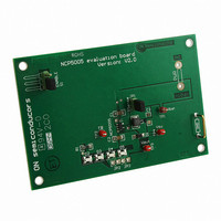
EVAL BOARD FOR NCP5005G
Manufacturer
ON Semiconductor
Specifications of NCP5005GEVB
Design Resources
NCP5005 EVB BOM NCP5005GEVB Gerber Files NCP5005 EVB Schematic
Outputs And Type
1, Non-Isolated
Voltage - Output
22V
Voltage - Input
3.6V
Utilized Ic / Part
NCP5005
Core Chip
NCP5005
Topology
Boost
No. Of Outputs
1
Development Tool Type
Hardware - Eval/Demo Board
Leaded Process Compatible
Yes
Mcu Supported Families
NCP5005SNT1G
Rohs Compliant
Yes
Lead Free Status / RoHS Status
Lead free / RoHS Compliant
Features
-
Current - Output / Channel
-
Lead Free Status / Rohs Status
Lead free / RoHS Compliant
For Use With/related Products
NCP5005G
Other names
NCP5005GEVBOS


Discontinuous Mode of Operation Analysis
large peak current takes place in the inductor as depicted in
Figure 6. The PWM mode is prone to such a discontinuous
cycle. The output voltage is largely different, in comparison
with the NCP5007, as one expects from a discontinuous
mode of operation. The main consequence is the large
oscillations developed when the transfer of the current
between the inductor and the load is completed. Of course,
internal circuit can be implemented to avoid such oscillation
(so-called ring killer), but all ICs might not have such
features. The oscillations are no longer the only
consequence of the Schottky diode, but come from the main
inductor (22 mH) associated with the stray capacitances.
Assuming we have a 30 pF stray capacitance (the Schottky
When a chip operates in a fully discontinuous mode, a
Figure 6. Typical PWM Normal Operation
http://onsemi.com
AND8172/D
6
diode as a minimum parasitic capacitance since the reverse
voltage is maximum), the frequency is 6.2 MHz, yielding a
161 ns period. The calculated values are well within the
evaluation tests carried out with a PWM based white LED
driver used as a reference (Figure 6, top trace).
during this period:
inductor and this element is prone to radiate most of this
energy out of the core, unless a shielding magnetic core is
used.
Ej + 1
Ej + 1
At this point, one can derive the level of energy radiated
Although such a level is low, is it generated by the main
2
2
* L * I 2
* 22 * 10 -6 * 0.04 2 + 4.4 nJ
(I = level of the current during the oscillation
first order only)
(eq. 5)
Related parts for NCP5005GEVB
Image
Part Number
Description
Manufacturer
Datasheet
Request
R

Part Number:
Description:
Compact Backlight LED Boost Driver
Manufacturer:
ON Semiconductor
Datasheet:
Part Number:
Description:
ON Semiconductor [VOLTAGE REGULATOR]
Manufacturer:
ON Semiconductor
Datasheet:
Part Number:
Description:
357-036-542-201 CARDEDGE 36POS DL .156 BLK LOPRO
Manufacturer:
ON Semiconductor
Datasheet:
Part Number:
Description:
357-036-542-201 CARDEDGE 36POS DL .156 BLK LOPRO
Manufacturer:
ON Semiconductor
Datasheet:
Part Number:
Description:
357-036-542-201 CARDEDGE 36POS DL .156 BLK LOPRO
Manufacturer:
ON Semiconductor
Datasheet:
Part Number:
Description:
357-036-542-201 CARDEDGE 36POS DL .156 BLK LOPRO
Manufacturer:
ON Semiconductor
Datasheet:
Part Number:
Description:
357-036-542-201 CARDEDGE 36POS DL .156 BLK LOPRO
Manufacturer:
ON Semiconductor
Datasheet:
Part Number:
Description:
357-036-542-201 CARDEDGE 36POS DL .156 BLK LOPRO
Manufacturer:
ON Semiconductor
Datasheet:
Part Number:
Description:
357-036-542-201 CARDEDGE 36POS DL .156 BLK LOPRO
Manufacturer:
ON Semiconductor
Datasheet:
Part Number:
Description:
357-036-542-201 CARDEDGE 36POS DL .156 BLK LOPRO
Manufacturer:
ON Semiconductor
Datasheet:
Part Number:
Description:
357-036-542-201 CARDEDGE 36POS DL .156 BLK LOPRO
Manufacturer:
ON Semiconductor
Datasheet:
Part Number:
Description:
357-036-542-201 CARDEDGE 36POS DL .156 BLK LOPRO
Manufacturer:
ON Semiconductor
Datasheet:
Part Number:
Description:
Manufacturer:
ON Semiconductor
Datasheet:
Part Number:
Description:
Manufacturer:
ON Semiconductor
Datasheet: