AS1112 EB austriamicrosystems, AS1112 EB Datasheet - Page 2
AS1112 EB
Manufacturer Part Number
AS1112 EB
Description
BOARD EVAL AS1112
Manufacturer
austriamicrosystems
Specifications of AS1112 EB
Current - Output / Channel
0.5 ~ 100 mA
Outputs And Type
16, Non-Isolated
Voltage - Output
0 ~ 15 V
Features
Over-Temperature, Open-LED, Shorted-LED, Diagnostics
Voltage - Input
3 ~ 5.5 V
Utilized Ic / Part
AS1112
Lead Free Status / RoHS Status
Lead free by exemption / RoHS compliant by exemption


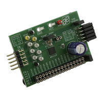
Figure 1: Evalboard Description
AS1112 - Evaluation Board
Application Note
General Description
Board Description
Supply Description
Label
A
B
C
Connector Description
Label
D
E
F
Components Connectors Description
Label
G
H
I
J
K
www.austriamicrosystems.com
Name
VCC
GND
VLED
Name
IN
OUT
XERR
GSCK
LD
SDI
GND
SDO
OEN
CLK
MODE
Name
SDO Termin.
Power Down
Rext
OUTN0-15
CLED
Description
Power Supply Connectors for
VDD and Ground.
Supply Voltage for the LED’s
Description
Line In Connector
Line Out Connector
Measurement Points
Error Output
Greyscale Clock
Data Latch
Serial Data Input
Ground
Serial Data Output
Output Enable
Serial Data Clock
Mode Select
Description
External Resistor
Output Current Drivers
Decoupling Capacity of LEDs
Revision 1.00
+3.0V to +5.5V
The output current drivers of the AS1112 can handle up to +15V.
Can be directly connected to OUT (E) of the previous board.
Can be directly connected to IN (D) of the next board.
Description follows below.
0: Open or Temp. Error Detected 1: Normal Operation
Reference clock for grayscale PWM control.
(MODE = GND): the greyscale register receives new data.
(MODE = VCC): the dot correction register receives new data.
0 = OUTn outputs are controlled by the greyscale PWM control.
1 = OUTn outputs are forced off; the greyscale counter is reset.
Input with internal pulldown
MODE = GND: Selects greyscale mode
MODE = VCC: Selects dot correction mode
This jumper must be set if only a single board is in use, or on the
last board in a daisy chain.
Input with internal pulldown
0 = normal operation mode
1 = powerdown mode
Place resistor here to set the load current.
Connector for LED’s. Upper side interfaces with the output drivers
of the AS1112 while the bottom line connects to VLED.
Jumper to (dis)connect the onboard capacity.
Info
Info
Info
Figure 3: Output Line (E)
Figure 2: Input Line (D)
2 - 5
Related parts for AS1112 EB
Image
Part Number
Description
Manufacturer
Datasheet
Request
R

Part Number:
Description:
IC DRIVER LED 16-CHAN 32-TQFN
Manufacturer:
austriamicrosystems
Datasheet:

Part Number:
Description:
16-Channel LED Driver
Manufacturer:
austriamicrosystems AG
Datasheet:
Part Number:
Description:
IC SWITCH QUAD SPST 14-TSSOP
Manufacturer:
austriamicrosystems
Datasheet:
Part Number:
Description:
IC SWITCH QUAD SPST 14-TSSOP
Manufacturer:
austriamicrosystems
Datasheet:
Part Number:
Description:
IC AMP AUDIO MONO 1.8W 10-MSOP
Manufacturer:
austriamicrosystems
Datasheet:
Part Number:
Description:
IC AMP AUDIO MONO 1.8W 10-MSOP
Manufacturer:
austriamicrosystems
Datasheet:
Part Number:
Description:
IC AMP AUDIO MONO 1.8W 10-MSOP
Manufacturer:
austriamicrosystems
Datasheet:
Part Number:
Description:
IC AMP AUD 1.8W 3DB GAIN 10-MSOP
Manufacturer:
austriamicrosystems
Datasheet:
Part Number:
Description:
IC DRIVER LED 8-DIGIT 24-SOIC
Manufacturer:
austriamicrosystems
Datasheet:
Part Number:
Description:
IC DRIVER LED 8-DIGIT 24-SOIC
Manufacturer:
austriamicrosystems
Datasheet:
Part Number:
Description:
IC, LINE/SPEAKER PHONE CIRCUIT, SOIC-28
Manufacturer:
austriamicrosystems
Datasheet:
Part Number:
Description:
IC MULTI-STANDARD CMOS TELEPHONE SOIC-28
Manufacturer:
austriamicrosystems
Datasheet:
Part Number:
Description:
IC MULTI-STANDARD CMOS TELEPHONE SOIC-28
Manufacturer:
austriamicrosystems
Datasheet:
Part Number:
Description:
IC MULTI-STANDARD CMOS TELEPHONE SOIC-28
Manufacturer:
austriamicrosystems
Datasheet:
Part Number:
Description:
CABGA 64 (7x7)
Manufacturer:
austriamicrosystems
Datasheet: