AD8332-EVALZ Analog Devices Inc, AD8332-EVALZ Datasheet - Page 43
AD8332-EVALZ
Manufacturer Part Number
AD8332-EVALZ
Description
BOARD EVAL FOR AD8332
Manufacturer
Analog Devices Inc
Series
X-AMP®r
Specifications of AD8332-EVALZ
Channels Per Ic
1 - Single
Amplifier Type
Variable Gain
Output Type
Differential
Slew Rate
1100 V/µs
-3db Bandwidth
100MHz
Current - Output / Channel
45mA
Operating Temperature
-40°C ~ 85°C
Current - Supply (main Ic)
27.5mA
Voltage - Supply, Single/dual (±)
4.5 V ~ 5.5 V
Board Type
Fully Populated
Utilized Ic / Part
AD8332
Silicon Manufacturer
Analog Devices
Application Sub Type
Variable Gain Amplifier
Kit Application Type
Amplifier
Silicon Core Number
AD8332
Kit Contents
Board
Lead Free Status / RoHS Status
Lead free / RoHS Compliant


AD8332 EVALUATION BOARD
GENERAL DESCRIPTION
The AD8332-EVALZ is a platform for the testing and evaluation of
the
assembled and tested, and users need only connect the signal
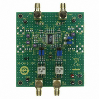
and VGAIN sources to a single 5 V power supply. Figure 104 is a
photograph of the component side of the board, and Figure 105
shows the schematic. The AD8332-EVALZ is lead free and
RoHS compliant.
USER-SUPPLIED OPTIONAL COMPONENTS
The board is built and tested using the components shown in
black in Figure 105. Provisions are made for optional components
(shown in gray) that can be installed for testing at user discretion.
The default LNA input impedance is 50 Ω to match various
signal generators and network analyzers. Input impedances up to
6 kΩ are realized by changing the values of RFBx and CSHx. For
reference, Table 11 lists the common input impedance values
and corresponding adjustments. The board is designed for 0603
size, surface-mount components.
AD8332
variable gain amplifier (VGA). The board is shipped
Figure 104.Photograph of the AD8332-EVALZ
Rev. G | Page 43 of 56
Table 11. LNA External Component Values for Common
Source Impedances
R
50
75
100
200
500
6 k
SMA connectors, S2, S3, S6, and S7, are provided for access to
the LNA outputs or the VGA inputs. If the LNA is used alone,
0.1 μF coupling capacitors can be installed at the C5, C9, C23,
and C24 locations. Resistors of 68 Ω to 100 Ω may be required
if the load capacitances, as seen by the LNA outputs, are larger
than approximately 10 pF.
A resistor can be inserted at RCLMP if output clamping is desired.
The peak-to-peak clamping level is adjusted by installing one of
the standard 1% resistor values listed in Table 8.
A high frequency differential probe connected to the 2-pin headers,
VOx, is the preferred method to observe a waveform at the VGA
output. A typical setup is shown in Figure 106. Single-ended loads
can be connected directly via the board edge SMA connectors.
Note that the AD8332 output amplifier is buffered with 237 Ω
resistors; therefore, be sure to compensate for attenuation if low
impedances are connected to the output SMAs.
MEASUREMENT SETUP
The basic board connections for measuring bandwidth are
shown in Figure 106. A 5 V, 100 mA (minimum) power supply
is required, and a low noise voltage reference supply is required
for VGAIN.
BOARD LAYOUT
The evaluation board circuitry uses four conductor layers.
The two inner layers are power and ground planes, and all
interconnecting circuitry is located on the outer layers. Figure 108
to Figure 111 illustrate the copper patterns.
IN
(Ω)
RFB1, RFB2 (Ω Std 1% Value)
274
412
562
1.13 k
3.01 k
∞
AD8331/AD8332/AD8334
CSH1, CSH2 (pF)
22
12
8
1.2
None
None
Related parts for AD8332-EVALZ
Image
Part Number
Description
Manufacturer
Datasheet
Request
R

Part Number:
Description:
BOARD EVAL FOR AD8332
Manufacturer:
Analog Devices Inc
Datasheet:

Part Number:
Description:
±1.7g Dual-Axis IMEMS Accelerometer Evaluation Board
Manufacturer:
Analog Devices Inc
Datasheet:

Part Number:
Description:
Inertial Sensor Evaluation System
Manufacturer:
Analog Devices Inc
Datasheet:
Part Number:
Description:
Manufacturer:
Analog Devices Inc
Datasheet:
Part Number:
Description:
Manufacturer:
Analog Devices Inc
Datasheet:
Part Number:
Description:
Manufacturer:
Analog Devices Inc
Datasheet:
Part Number:
Description:
Manufacturer:
Analog Devices Inc
Datasheet:
Part Number:
Description:
Manufacturer:
Analog Devices Inc
Datasheet:
Part Number:
Description:
Manufacturer:
Analog Devices Inc
Datasheet:
Part Number:
Description:
Manufacturer:
Analog Devices Inc
Datasheet:
Part Number:
Description:
Manufacturer:
Analog Devices Inc
Datasheet:
Part Number:
Description:
Manufacturer:
Analog Devices Inc
Datasheet:
Part Number:
Description:
Manufacturer:
Analog Devices Inc
Datasheet: