MCP6XXXEV-AMP1 Microchip Technology, MCP6XXXEV-AMP1 Datasheet - Page 18
MCP6XXXEV-AMP1
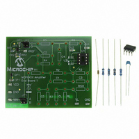
Manufacturer Part Number
MCP6XXXEV-AMP1
Description
BOARD AMPLIFIER EVAL 1 MCP6XXX
Manufacturer
Microchip Technology
Datasheet
1.MCP6XXXEV-AMP1.pdf
(42 pages)
Specifications of MCP6XXXEV-AMP1
Channels Per Ic
1 - Single
Amplifier Type
General Purpose
Board Type
Partially Populated
Utilized Ic / Part
8-DIP Package
Processor To Be Evaluated
MCP6xxx
Lead Free Status / RoHS Status
Lead free / RoHS Compliant
Operating Temperature
-
Output Type
-
Current - Output / Channel
-
Voltage - Supply, Single/dual (±)
-
-3db Bandwidth
-
Slew Rate
-
Current - Supply (main Ic)
-
Lead Free Status / Rohs Status
Lead free / RoHS Compliant
Available stocks
Company
Part Number
Manufacturer
Quantity
Price
Company:

Part Number:
MCP6XXXEV-AMP1
Manufacturer:
MICROCHIP
Quantity:
12 000
Part Number:
MCP6XXXEV-AMP1
Manufacturer:
MICROCHIP/微芯
Quantity:
20 000


MCP6XXX Amplifier Evaluation Board 1 User’s Guide
DS51667A-page 14
2.3.1.7
• Compares the input voltage to another (reference) voltage and forces the output
• The Mindi™ Amplifier Designer gives design recommendations for the inverting
Note: The MCP6XXX Amplifier Evaluation Board 1 currently only supports the inverting
comparator with center trip point = 2.5V.
FIGURE 2-12:
Figure 2-13 shows an example of the inverting comparator circuit diagram supported
by MCP6XXX Amplifier Evaluation Board 1.
FIGURE 2-13:
Amplifier Evaluation Board 1.
* Test Points
to one of two digital states. Input signal is applied to the inverting input. The
comparison includes a user selected amount of hysteresis. Input and output
voltages are shifted by a reference for single supply
comparator circuit; see the circuit diagram shown in Figure 2-12
- Fill the sockets with the recommended resistors and capacitors
- Set JP1 and JP2 in the correct positions
(for the given example, JP1: Position B, JP2: Position C)
CR2
0.1 µF
GND
VDD
Power Supply
VIN
INVERTING COMPARATOR
Mid-supply
Reference
RR1
20 kΩ
RR2
20 kΩ
V
JP1
DP1
IN
Inverting Comparator Circuit Diagram.
Inverting Comparator Example Supported by the MCP6XXX
VDD
A
B
1.0 µF
0.1 µF
CP1
R
CR1
UR1
V
1
R
VREF
R
5
C
5
R
R1
C2
R4
JP2
6
V
DD
C5
C
D
C
U1
U
1
R5
R7
V
OUT
Supply
Power
CL
V S
R2
C1
C4
Output
© 2007 Microchip Technology Inc.
Load
RL
VDD
VL
R6
V
U1
L
0.1 µF
R3
C3
CU1
RISO
GND
Related parts for MCP6XXXEV-AMP1
Image
Part Number
Description
Manufacturer
Datasheet
Request
R

Part Number:
Description:
BOARD AMPLIFIER EVAL 4 MCP6XXX
Manufacturer:
Microchip Technology
Datasheet:

Part Number:
Description:
BOARD AMPLIFIER EVAL 3 MCP6XXX
Manufacturer:
Microchip Technology
Datasheet:

Part Number:
Description:
BOARD AMPLIFIER EVAL 2 MCP6XXX
Manufacturer:
Microchip Technology
Datasheet:

Part Number:
Description:
Manufacturer:
Microchip Technology Inc.
Datasheet:
Part Number:
Description:
Manufacturer:
Microchip Technology Inc.
Datasheet:
Part Number:
Description:
Manufacturer:
Microchip Technology Inc.
Datasheet:
Part Number:
Description:
Manufacturer:
Microchip Technology Inc.
Datasheet:
Part Number:
Description:
Manufacturer:
Microchip Technology Inc.
Datasheet:
Part Number:
Description:
Manufacturer:
Microchip Technology Inc.
Datasheet:
Part Number:
Description:
Manufacturer:
Microchip Technology Inc.
Datasheet: