E100S Atmel, E100S Datasheet - Page 3
E100S
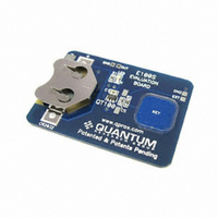
Manufacturer Part Number
E100S
Description
KIT EVAL FOR QT100
Manufacturer
Atmel
Series
Quantum, QTouch™r
Specifications of E100S
Sensor Type
Touch, Capacitive
Sensing Range
1 Button/Key
Interface
Logic Level
Voltage - Supply
3V
Embedded
No
Utilized Ic / Part
QT100
Lead Free Status / RoHS Status
Lead free / RoHS Compliant
Sensitivity
-
Lead Free Status / Rohs Status
Lead free / RoHS Compliant
For Use With/related Products
QT100-ISG
Other names
427-1128


1 Overview
1.1 Introduction
The QT100 is a digital burst mode charge-transfer (QT)
sensor designed specifically for touch controls; it includes all
hardware and signal processing functions necessary to
provide stable sensing under a wide variety of changing
conditions. Only a single low cost, noncritical capacitor is
required for operation.
Figure 1.1 shows a basic circuit using the device.
1.2 Basic Operation
The QT100 employs bursts of charge-transfer cycles to
acquire its signal. Burst mode permits power consumption in
the microamp range, dramatically reduces RF emissions,
lowers susceptibility to EMI, and yet permits excellent
response time. Internally the signals are digitally processed to
reject impulse noise, using a 'consensus' filter which requires
four consecutive confirmations of a detection before the output
is activated.
The QT switches and charge measurement hardware
functions are all internal to the QT100.
1.3 Electrode Drive
For optimum noise immunity, the electrode should only be
connected to SNSK.
In all cases the rule Cs >> Cx must be observed for proper
operation; a typical load capacitance (Cx) ranges from 5-20pF
while Cs is usually about 2-50nF.
Increasing amounts of Cx destroy gain, therefore it is
important to limit the amount of stray capacitance on both
SNS terminals. This can be done, for example, by minimizing
trace lengths and widths and keeping these traces away from
power or ground traces or copper pours.
The traces and any components associated with SNS and
SNSK will become touch sensitive and should be treated with
caution to limit the touch area to the desired location.
A series resistor, Rs, should be placed in line with SNSK to
the electrode to suppress ESD and EMC effects.
1.4 Sensitivity
1.4.1 Introduction
The sensitivity on the QT100 is a function of things like the
value of Cs, electrode size and capacitance, electrode shape
and orientation, the composition and aspect of the object to be
sensed, the thickness and composition of any overlaying
panel material, and the degree of ground coupling of both
sensor and object.
1.4.2 Increasing Sensitivity
In some cases it may be desirable to increase sensitivity; for
example, when using the sensor with very thick panels having
a low dielectric constant. Sensitivity can often be increased by
using a larger electrode or reducing panel thickness.
Increasing electrode size can have diminishing returns, as
high values of Cx will reduce sensor gain.
lQ
3
The value of Cs also has a dramatic effect on sensitivity, and
this can be increased in value with the trade-off of slower
response time and more power. Increasing the electrode's
surface area will not substantially increase touch sensitivity if
its diameter is already much larger in surface area than the
object being detected. Panel material can also be changed to
one having a higher dielectric constant, which will better help
to propagate the field.
Ground planes around and under the electrode and its SNSK
trace will cause high Cx loading and destroy gain. The
possible signal-to-noise ratio benefits of ground area are more
than negated by the decreased gain from the circuit, and so
ground areas around electrodes are discouraged. Metal areas
near the electrode will reduce the field strength and increase
Cx loading and should be avoided, if possible. Keep ground
away from the electrodes and traces.
1.4.3 Decreasing Sensitivity
In some cases the QT100 may be too sensitive. In this case
gain can be easily lowered further by decreasing Cs.
2 Operation Specifics
2.1 Run Modes
2.1.1 Introduction
The QT100 has three running modes which depend on the
state of SYNC, pin 6 (high or low).
2.1.2 Fast Mode
The QT100 runs in Fast mode if the SYNC pin is permanently
high. In this mode the QT100 runs at maximum speed at the
expense of increased current consumption. Fast mode is
useful when speed of response is the prime design
requirement. The delay between bursts in Fast mode is
approximately 1ms, as shown in Figure 2.2.
2.1.3 Low Power Mode
The QT100 runs in Low Power (LP) mode if the SYNC line is
held low. In this mode it sleeps for approximately 85ms at the
end of each burst, saving power but slowing response. On
detecting a possible key touch, it temporarily switches to Fast
mode until either the key touch is confirmed or found to be
spurious (via the detect integration process). It then returns to
LP mode after the key touch is resolved as shown in
Figure 2.1.
Figure 1.1 Basic Circuit Configuration
1
OUT
Note: A bypass capacitor should be tightly wired
between Vdd and Vss and kept close to QT100 pin 5.
SYNC/MODE
VDD
VDD
VSS
5
2
SNSK
SNS
3
4
6
QT100_3R0.09_0707
Cs
Rs
ELECTRODE
SENSE
Cx
Related parts for E100S
Image
Part Number
Description
Manufacturer
Datasheet
Request
R

Part Number:
Description:
DEV KIT FOR AVR/AVR32
Manufacturer:
Atmel
Datasheet:

Part Number:
Description:
INTERVAL AND WIPE/WASH WIPER CONTROL IC WITH DELAY
Manufacturer:
ATMEL Corporation
Datasheet:
Part Number:
Description:
Low-Voltage Voice-Switched IC for Hands-Free Operation
Manufacturer:
ATMEL Corporation
Datasheet:
Part Number:
Description:
MONOLITHIC INTEGRATED FEATUREPHONE CIRCUIT
Manufacturer:
ATMEL Corporation
Datasheet:
Part Number:
Description:
AM-FM Receiver IC U4255BM-M
Manufacturer:
ATMEL Corporation
Datasheet:
Part Number:
Description:
Monolithic Integrated Feature Phone Circuit
Manufacturer:
ATMEL Corporation
Datasheet:
Part Number:
Description:
Multistandard Video-IF and Quasi Parallel Sound Processing
Manufacturer:
ATMEL Corporation
Datasheet:
Part Number:
Description:
High-performance EE PLD
Manufacturer:
ATMEL Corporation
Datasheet:
Part Number:
Description:
8-bit Flash Microcontroller
Manufacturer:
ATMEL Corporation
Datasheet:
Part Number:
Description:
2-Wire Serial EEPROM
Manufacturer:
ATMEL Corporation
Datasheet: