ATAVRQTOUCHX Atmel, ATAVRQTOUCHX Datasheet - Page 169
ATAVRQTOUCHX
Manufacturer Part Number
ATAVRQTOUCHX
Description
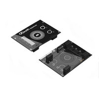
BOARD EVAL CAPACITIVE TOUCH
Manufacturer
Atmel
Series
QTouch™r
Specifications of ATAVRQTOUCHX
Sensor Type
Touch, Capacitive
Sensing Range
1 Slider, 1 Wheel, 2 Buttons
Interface
USB
Voltage - Supply
5V, USB
Embedded
Yes, MCU, 8-Bit
Utilized Ic / Part
AT90USB1287, ATxmega128A1
Silicon Manufacturer
Atmel
Silicon Family Name
ATxmega
Kit Contents
Board
Svhc
No SVHC (15-Dec-2010)
Core Architecture
AVR
Core Sub-architecture
AVR19
Kit Features
One Slider, One Wheel And 2
Rohs Compliant
Yes
Lead Free Status / RoHS Status
Lead free / RoHS Compliant
Sensitivity
-
Lead Free Status / Rohs Status
Lead free / RoHS Compliant
Available stocks
Company
Part Number
Manufacturer
Quantity
Price
Company:

Part Number:
ATAVRQTOUCHX
Manufacturer:
Atmel
Quantity:
135


6.5.5
The Table below describes the various configuration parameters corresponding to the ATtiny40
QTouch Library.
DEF_QT_DI
DEF_QT_NEG_DRIFT_RATE*(See Note 1)
DEF_QT_POS_DRIFT_RATE*(See Note 1)
DEF_QT_MAX_ON_DURATION
DEF_QT_DRIFT_HOLD_TIME
DEF_QT_POS_RECAL_DELAY
DEF_QT_SIGNAL_RESOLUTION
Note1:
For the case of ATtiny40 devices, a ‘touch’ causes the Signal value measured on the Sensor to
increase above the Sensor Reference value (In the case of Generic Library devices, a ‘touch’
causes the Signal value to decrease below the Reference value).
However, the Negative drift rate and Positive drift rate functionality for the case of Tiny40 devices
shall be consistent with the Generic Library case.
So, it is recommended to have a ‘Slower’ Negative Drift rate (4 seconds is the default setting) and
a ‘Faster’ Positive Drift rate (1 second is the default setting) for the Tiny40 device.
6.5.6
The QTouch method IAR Example project for the Tiny40 Evaluation Kit can be found in the
following path.
\Device_Specific_Libraries\8bit_AVR\AVR_Tiny_Mega_XMega\ATtiny40\tiny40_qt_example_iar
The Example projects demonstrate the 12 button sensor configuration. The Example projects
also support QDebug data transfer to QTouch Studio – Touch Analyzer PC Application.
It is possible to configure the number of Sensors in the Example project from 1 to 12 for testing
on the ATtiny40 Evaluation kit.
QTouch Library configuration parameters for ATtiny40
QTouch Library ATtiny40 Example projects
Parameter
Table 21 QTouch Library for ATtiny40 Configuration parameters
Sensor detect integration (DI) limit.Range: 0u to 255u.
Refer
Sensor negative drift rate. Units: 100ms, Range: 1u to 127u.
Refer
Sensor positive drift rate. Units: 100ms, Range: 1u to 127u.
Refer
Sensor maximum on duration. Units: 100ms, Range: 0u to 255u.
Refer
Sensor drift hold time. Units: 100ms, Range: 1u to 255u.
Refer
Positive Recalibration delay. Range: 1u to 255u.
Refer
Signal Resolution. Range: 10u – 12u. Proper function for values more
than 12u is not guaranteed.
Section 5.3
Section 5.3
Section 5.3
Section 5.3
Section 5.3
Section 5.3
and
and
and
and
and
and
Section 5.4
Section 5.4
Section 5.4
Section 5.4
Section 5.4
Section 5.4
Description
for more info.
for more info.
for more info.
for more info.
for more info.
for more info.
169
Related parts for ATAVRQTOUCHX
Image
Part Number
Description
Manufacturer
Datasheet
Request
R


Part Number:
Description:
DEV KIT FOR AVR/AVR32
Manufacturer:
Atmel
Datasheet:

Part Number:
Description:
INTERVAL AND WIPE/WASH WIPER CONTROL IC WITH DELAY
Manufacturer:
ATMEL Corporation
Datasheet:
Part Number:
Description:
Low-Voltage Voice-Switched IC for Hands-Free Operation
Manufacturer:
ATMEL Corporation
Datasheet:
Part Number:
Description:
MONOLITHIC INTEGRATED FEATUREPHONE CIRCUIT
Manufacturer:
ATMEL Corporation
Datasheet:
Part Number:
Description:
AM-FM Receiver IC U4255BM-M
Manufacturer:
ATMEL Corporation
Datasheet:
Part Number:
Description:
Monolithic Integrated Feature Phone Circuit
Manufacturer:
ATMEL Corporation
Datasheet:
Part Number:
Description:
Multistandard Video-IF and Quasi Parallel Sound Processing
Manufacturer:
ATMEL Corporation
Datasheet:
Part Number:
Description:
High-performance EE PLD
Manufacturer:
ATMEL Corporation
Datasheet:
Part Number:
Description:
8-bit Flash Microcontroller
Manufacturer:
ATMEL Corporation
Datasheet:
Part Number:
Description:
2-Wire Serial EEPROM
Manufacturer:
ATMEL Corporation
Datasheet: