TMPSNS-RTD1 Microchip Technology, TMPSNS-RTD1 Datasheet - Page 11
TMPSNS-RTD1
Manufacturer Part Number
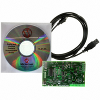
TMPSNS-RTD1
Description
BOARD EVAL PT100 RTD TEMP SENSOR
Manufacturer
Microchip Technology
Datasheets
1.MCP3301-CIMS.pdf
(32 pages)
2.PCM18XR1.pdf
(438 pages)
3.MCP6S22DM-PICTL.pdf
(43 pages)
4.TMPSNS-RTD1.pdf
(26 pages)
Specifications of TMPSNS-RTD1
Sensor Type
Temperature
Interface
USB
Embedded
Yes, MCU, 8-Bit
Utilized Ic / Part
MCP3301, MCP6S26, PIC18F2550
Processor To Be Evaluated
MCP6S26, MCP3301, MCP6024, MCP41010, PIC18F2550, TC1071, MCP6002
Data Bus Width
12 bit
Interface Type
USB
Lead Free Status / RoHS Status
Not applicable / Not applicable
Voltage - Supply
-
Sensitivity
-
Sensing Range
-
Lead Free Status / RoHS Status
Lead free / RoHS Compliant, Not applicable / Not applicable


2.1
2.2
© 2007 Microchip Technology Inc.
INTRODUCTION
FEATURES
Chapter 2. Installation and Operation
The PT100 RTD Evaluation Board allows the user to evaluate Microchip’s solution to
accurately measure temperature using RTD. When biasing RTDs to measure
temperature, self-heat due to power dissipation has to be considered. RTD resistance
availability typically ranges from 100Ω to 5,000Ω. In order to measure the output
voltage across the RTD over a wide temperature range, the biasing current has to be
relatively high. This higher current causes more power dissipation through heat and
skews the temperature reading. Microchip’s solution to this challenge is to use the
MCP6S26 Programmable Gain Amplifier (PGA) to increase the sensor dynamic output
range and increase measurement resolution while significantly reducing the biasing
current magnitude.
This board consists of a surface mount RTD to measure the PCB temperature and an
external RTD connector. In addition, the user can connect and measure an external
leaded RTD (2, 3, or 4-Wire) and configure the corresponding jumper to remotely
measure temperature. The multiple input channel PGA adds gain programmability into
the analog circuit. The multiple input channels are used to switch between RTDs and
the gain is used to increase the sensor dynamic range.
The PGA output is connected to a differential amplifier circuit which allows the user to
scale the sensor output. The differential output is digitized using an MCP3301 12-bit
differential analog-to-digital converter. The data is transmitted to the PC using the USB
interface. A PC Software Graphical User Interface (GUI) is used to obtain and display
the data in real-time.
The PT100 RTD Evaluation Board has the following features:
• A surface mount PT100 RTD
• External (2, 3, or 4-wire) RTD connector
• Gain and input channel programmability using MCP6S26 PGA
• MCP3301 12-Bit + sign ADC
• MCP41010 10 kΩ Digital Potentiometer
• PIC18F2550 PICmicro
• USB interface to PC
• PC Software GUI
®
Microcontroller
PT100 RTD EVALUATION
BOARD USER’S GUIDE
DS51607B-page 7
Related parts for TMPSNS-RTD1
Image
Part Number
Description
Manufacturer
Datasheet
Request
R

Part Number:
Description:
Manufacturer:
Microchip Technology Inc.
Datasheet:
Part Number:
Description:
Manufacturer:
Microchip Technology Inc.
Datasheet:
Part Number:
Description:
Manufacturer:
Microchip Technology Inc.
Datasheet:
Part Number:
Description:
Manufacturer:
Microchip Technology Inc.
Datasheet:
Part Number:
Description:
Manufacturer:
Microchip Technology Inc.
Datasheet:
Part Number:
Description:
Manufacturer:
Microchip Technology Inc.
Datasheet:
Part Number:
Description:
Manufacturer:
Microchip Technology Inc.
Datasheet:
Part Number:
Description:
Manufacturer:
Microchip Technology Inc.
Datasheet: