DM164128 Microchip Technology, DM164128 Datasheet - Page 25
DM164128
Manufacturer Part Number
DM164128
Description
KIT DEV PICDEM TOUCH SENSE 2
Manufacturer
Microchip Technology
Series
mTouch™r
Specifications of DM164128
Sensor Type
Touch, Capacitive
Interface
Microprocessor
Embedded
Yes, MCU, 16-Bit
Utilized Ic / Part
PIC24F
Silicon Manufacturer
Microchip
Silicon Core Number
PIC24F256GB110
Features
ICSP Programming Capability, Directional Pad, Keypad And Slider Sensor
Kit Contents
Board
Lead Free Status / RoHS Status
Lead free / RoHS Compliant
Voltage - Supply
-
Sensitivity
-
Sensing Range
-
Lead Free Status / RoHS Status
Lead free / RoHS Compliant
Available stocks
Company
Part Number
Manufacturer
Quantity
Price
Company:

Part Number:
DM164128
Manufacturer:
Microchip Technology
Quantity:
135


4.2
FIGURE 4-3:
TABLE 4-1:
© 2008 Microchip Technology Inc.
Ref
10
1
2
3
4
5
6
7
8
9
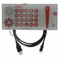
BOARD COMPONENTS
10
PIC24FJ256GB110 Microcontroller (U1)
USB mini-B Receptacle (J3)
ICSP™ Programming Header (J1)
Power Supply (D18, Q1)
Piezo Speaker (BZ1)
Directional Touch Sensor LEDs (D19-24, D26-27, D38)
Directional Touch Sensor Area – Front of Board (ROT1)
Numeric Keypad Area – Sensors on Front of Board (S1-12, S21-28, D1-10, D28-37)
Touch Slider Area – Sensor on Front of Board (S14, D12-17, D39-64)
Power Touch Switch – Sensor on Front of Board (S20, D65)
BOARD COMPONENTS
The microcontroller uses its on-chip USB engine and transceiver to communicate the
PC side interface application, using the USB mini-B receptacle. The demo board also
uses the USB receptacle for application power as a bus-powered device.
Microcontroller and LED power is provided from the V
regulator. Provisions on the board allow for users to add components and create an
externally powered application.
For users interested in using the Touch Sense 2 Demo Board as an experimental
platform, the microcontroller can be reprogrammed through a standard interface. A
six-pin header is provided for connecting the demo board to any MPLAB ICD 2
compatible programmer. Since the ICD interface shares some input lines with the
numeric keypad interface, a separate switch (S13, not shown in the figure) allows users
to connect or disconnect the ICD lines from the scan lines. While this is not strictly
necessary, it does help to reduce the overall capacitance of the touch pads.
Figure 4-3 identifies the key hardware components for the demo board. Note that the
active components are mounted to the bottom side of the board; only the touch sensors
are on the front side.
TOUCH SENSE 2 DEMO BOARD COMPONENT LAYOUT (BOTTOM SIDE)
9
1
2
Component
8
3
Demo Board Hardware
4
BUS
by Q1, an MCP1702 voltage
7
6
DS51748A-page 21
5
Related parts for DM164128
Image
Part Number
Description
Manufacturer
Datasheet
Request
R

Part Number:
Description:
Manufacturer:
Microchip Technology Inc.
Datasheet:
Part Number:
Description:
Manufacturer:
Microchip Technology Inc.
Datasheet:
Part Number:
Description:
Manufacturer:
Microchip Technology Inc.
Datasheet:
Part Number:
Description:
Manufacturer:
Microchip Technology Inc.
Datasheet:
Part Number:
Description:
Manufacturer:
Microchip Technology Inc.
Datasheet:
Part Number:
Description:
Manufacturer:
Microchip Technology Inc.
Datasheet:
Part Number:
Description:
Manufacturer:
Microchip Technology Inc.
Datasheet:
Part Number:
Description:
Manufacturer:
Microchip Technology Inc.
Datasheet: