STEVAL-MKI078V1 STMicroelectronics, STEVAL-MKI078V1 Datasheet - Page 11
STEVAL-MKI078V1
Manufacturer Part Number
STEVAL-MKI078V1
Description
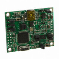
BOARD DEMO LPR450AL GYROSCOPE
Manufacturer
STMicroelectronics
Series
MEMSr
Datasheets
1.STEVAL-MKI009V1.pdf
(42 pages)
2.STEVAL-MKI099V1.pdf
(35 pages)
3.STEVAL-MKI078V1.pdf
(4 pages)
Specifications of STEVAL-MKI078V1
Design Resources
STEVAL-MKI078V1 Schematic
Sensor Type
Gyroscope, 2 Axis
Sensing Range
±500°/sec
Interface
Analog and Digital
Sensitivity
2mV/°/s
Voltage - Supply
5V, USB
Embedded
Yes, MCU, 8-Bit
Utilized Ic / Part
LPR450AL
Interface Type
GUI, USB
Lead Free Status / RoHS Status
Lead free / RoHS Compliant
For Use With/related Products
LPR450AL
Other names
497-10600
Available stocks
Company
Part Number
Manufacturer
Quantity
Price
Company:

Part Number:
STEVAL-MKI078V1
Manufacturer:
STMicroelectronics
Quantity:
1


UM0701
5.1.4
The CN13-4-pin of the STM3210B-EVAL is also used by the Tamper button. The Tamper
button cannot be used when using the Int2 signal.
Figure 7.
Setup for digital MEMS - I
Position the JP7 and JP12 jumpers on the STM32-MEMS board.
If Int1 signal is used
Position the JP10 jumper on the STM32-MEMS board.
The CN13-14-pin of the STM3210B-EVAL is also used by the right joystick. If the joystick is
required, remove R75 from the STM3210B-EVAL board.
If Int2 signal is used
Position the JP11 jumper on the STM32-MEMS board.
The CN13-4-pin of the STM3210B-EVAL is also used by the Tamper button. The Tamper
button cannot be used when using the Int2 signal.
Figure 8.
Setup for digital MEMS - SPI interface
Setup for digital MEMS - I
Doc ID 15703 Rev 1
2
C interface
2
C interface
System setup
11/42
Related parts for STEVAL-MKI078V1
Image
Part Number
Description
Manufacturer
Datasheet
Request
R

Part Number:
Description:
BOARD EVAL FOR MEMS SENSORS
Manufacturer:
STMicroelectronics
Datasheet:

Part Number:
Description:
EVALBOARD/STEVAL-ISV014V1
Manufacturer:
STMicroelectronics
Part Number:
Description:
BOARD EVAL FOR ST802RT1
Manufacturer:
STMicroelectronics
Datasheet:

Part Number:
Description:
BOARD EVAL FOR VACUUM CLEANER
Manufacturer:
STMicroelectronics
Datasheet:

Part Number:
Description:
KIT DEV STARTER ST10F276Z5
Manufacturer:
STMicroelectronics
Datasheet:

Part Number:
Description:
BOARD LED CTLR/DVR STLED316S
Manufacturer:
STMicroelectronics
Datasheet:

Part Number:
Description:
BOARD EVAL BLDC SENSORLESS MOTOR
Manufacturer:
STMicroelectronics
Datasheet:

Part Number:
Description:
BOARD ELECT FISCAL CASH REGISTER
Manufacturer:
STMicroelectronics
Datasheet:

Part Number:
Description:
BOARD EVAL BIPO SOLUTION FOR PFC
Manufacturer:
STMicroelectronics
Datasheet:

Part Number:
Description:
BOARD EVAL UPS 450W VOUT=220V
Manufacturer:
STMicroelectronics
Datasheet:
Part Number:
Description:
STMicroelectronics [RIPPLE-CARRY BINARY COUNTER/DIVIDERS]
Manufacturer:
STMicroelectronics
Datasheet:
Part Number:
Description:
STMicroelectronics [LIQUID-CRYSTAL DISPLAY DRIVERS]
Manufacturer:
STMicroelectronics
Datasheet:
Part Number:
Description:
BOARD EVAL FOR MEMS SENSORS
Manufacturer:
STMicroelectronics
Datasheet: