STEVAL-MKI041V1 STMicroelectronics, STEVAL-MKI041V1 Datasheet
STEVAL-MKI041V1
Specifications of STEVAL-MKI041V1


Related parts for STEVAL-MKI041V1


STEVAL-MKI041V1 Summary of contents
Page 1
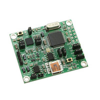
... This document applies to all demonstration kits related to ST MEMS single and double axis gyroscopes packages, hereafter referred to as “STEVAL-MKI0xxV1”. The STEVAL-MKI0xxV1 is a demonstration kit designed to provide the user with a complete, ready-to-use platform for demonstration of the LPR5xxxAL, LPY5xxxAL, LY5xxxALH product families. ...
Page 2
... Connecting to the virtual COM port . . . . . . . . . . . . . . . . . . . . . . . . . . . . . 14 4.2 GUI main window functions . . . . . . . . . . . . . . . . . . . . . . . . . . . . . . . . . . . 14 4.2.1 4.2.2 4.2.3 4.2.4 4.2.5 4.2.6 4.2.7 5 Data acquisition quick start . . . . . . . . . . . . . . . . . . . . . . . . . . . . . . . . . . 21 6 STEVAL-MKI0xxV1 Lite . . . . . . . . . . . . . . . . . . . . . . . . . . . . . . . . . . . . . . 22 7 Supported commands . . . . . . . . . . . . . . . . . . . . . . . . . . . . . . . . . . . . . . 23 7.1 Getting started . . . . . . . . . . . . . . . . . . . . . . . . . . . . . . . . . . . . . . . . . . . . . 23 7.2 Supported commands . . . . . . . . . . . . . . . . . . . . . . . . . . . . . . . . . . . . . . . 23 7.2.1 7.2.2 7.2.3 7.2.4 2/34 “Easy Start” button . . . . . . . . . . . . . . . . . . . . . . . . . . . . . . . . . . . . . . . . . 14 “ ...
Page 3
UM0796 7.2.5 7.2.6 7.3 Quick start . . . . . . . . . . . . . . . . . . . . . . . . . . . . . . . . . . ...
Page 4
... Plot tab . . . . . . . . . . . . . . . . . . . . . . . . . . . . . . . . . . . . . . . . . . . . . . . . . . . . . . . . . . . . . . . . 18 Figure 14. Plot tab - zoom . . . . . . . . . . . . . . . . . . . . . . . . . . . . . . . . . . . . . . . . . . . . . . . . . . . . . . . . . . 19 Figure 15. Data tab . . . . . . . . . . . . . . . . . . . . . . . . . . . . . . . . . . . . . . . . . . . . . . . . . . . . . . . . . . . . . . . 20 Figure 16. FFT tab . . . . . . . . . . . . . . . . . . . . . . . . . . . . . . . . . . . . . . . . . . . . . . . . . . . . . . . . . . . . . . . . 21 Figure 17. STEVAL-MKI0xxV1 Lite GUI . . . . . . . . . . . . . . . . . . . . . . . . . . . . . . . . . . . . . . . . . . . . . . . 23 Figure 18. Demonstration kit correctly recognized Figure 19. Select new firmware . . . . . . . . . . . . . . . . . . . . . . . . . . . . . . . . . . . . . . . . . . . . . . . . . . . . . . 28 Figure 20. Flash erasing . . . . . . . . . . . . . . . . . . . . . . . . . . . . . . . . . . . . . . . . . . . . . . . . . . . . . . . . . . . 29 Figure 21. Flash upgrading . . . . . . . . . . . . . . . . . . . . . . . . . . . . . . . . . . . . . . . . . . . . . . . . . . . . . . . . . 29 Figure 22. Schematic diagram of the STEVAL-MKI0xxV1 board . . . . . . . . . . . . . . . . . . . . . . . . . . . . 30 4/34 Doc ID 16227 Rev 1 UM0796 ...
Page 5
... UM0796 1 Demonstration kit description The STEVAL-MKI0xxV1 is a complete demonstration kit that allows evaluation of the performance of the LPR5xxxAL, LPY5xxxAL, LY5xxxALH low-power double/single-axis gyroscopes with analog outputs. The block diagram of the demonstration board included in the kit is shown in Figure 1. Demonstration board block diagram Analog ...
Page 6
... Operation of the STEVAL-MKI0xxV1 demonstration kit requires the installation of a dedicated driver which is included in the installation pack, together with a GUI interface which allows simple interaction with the sensor. The steps required for driver and software installation are described in the sections that follow. ...
Page 7
... UM0796 2 Working modes The STEVAL-MKI0xxV1 demonstration board is designed to be used in two different working modes: - Analog working mode (AWM): the microcontroller on the board is disabled and the analog outputs of the device are available to the user on the dedicated connector This is the default working mode when power is applied either through the USB connector or ...
Page 8
... A/D converter to read analog values from the device and to convert them in digital values, then sends them to the PC via the USB channel. For the board to work in DWM, the jumpers must be configured as described in Table 4. Jumper configuration for DWM Users can interact with the board by means of the STEVAL-MKI0xxV1 GUI and/or © Microsoft Hyper Terminal (refer to 8/34 ...
Page 9
UM0796 2.3 Additional settings JP2 must be present on the board to enable the DFU feature information on the DFU feature, see JP3 allows the measurement of current consumption J4 (usually open) is used to supply the board, alternatively, through ...
Page 10
... STEVAL-MKI0xxV1 GUI installation 3 STEVAL-MKI0xxV1 GUI installation The installation of the graphical user interface (GUI) for the STEVAL-MKI0xxV1 requires two steps: 1. installation of the software downloaded from 2. installation of the virtual COM driver needed to use the demonstration kit 3.1 PC system requirements Both the hardware and software that compose the STEVAL-MKI0xxV1 demonstration kit have been designed to operate with Microsoft 3 ...
Page 11
... Figure 6 and then Figure 6. Driver installation using the device manager Right click on My Computer Figure 5. Figure 7. Right click on “ST MEMS UNIT” and choose update driver Doc ID 16227 Rev 1 STEVAL-MKI0xxV1 GUI installation 7), follow the instructions on the (Figure AM01769v1 AM01770v1 11/34 ...
Page 12
... STEVAL-MKI0xxV1 GUI installation Figure 7. USB driver installation using the hardware update wizard Once the installation is complete, a COM port number is assigned to the ST virtual COM 8). This number should be retained required to run the STEVAL- driver (Figure MKI0xxV1 demonstration software GUI. For additional details, see section 4.1. ...
Page 13
... UM0796 Figure 8. Virtual COM driver port assignment STEVAL-MKI0xxV1 GUI installation Doc ID 16227 Rev 1 AM01772v1 13/34 ...
Page 14
... Graphical user interface 4 Graphical user interface To run the STEVAL-MKI0xxV1 demonstration software GUI: 1. Click on Start > All Programs. 2. Select STEVAL-MKI0xxV1 > Executables. 3. Launch the program “STEVAL-MKI0xxV1 Ver.0.0.1”. The GUI main window appears as shown in Figure 9. Graphical user interface: main window 14/34 Figure 9. ref 3 ref 1 ...
Page 15
... PC software. 4.1 Connecting to the virtual COM port Before using the functions of the demonstration kit software, the connection with the STEVAL-MKI0xxV1 board must be opened using the following steps: 1. Connect the STEVAL-MKI0xxV1 to the desired USB port the “Select COM” drop-down menu to which the board has been mapped. For additional information on how to obtain this number, see section 3.3. Otherwise, press “ ...
Page 16
Graphical user interface 4.2.2 “Home” tab This tab is used to show the codes of managed and recognized devices and demonstration 11). In case of unmanaged devices, a message is shown on the tab. boards (Figure Figure 10. Home tab ...
Page 17
UM0796 4.2.4 “Bars” tab The bars tab (Figure measured by the device in a bar chart format (see The height of the bar is determined by the amplitude of the signal measured around the axis. The full scale of the ...
Page 18
Graphical user interface 4.2.5 “Plot” tab The plot tab (Figure been measured by the MEMS sensor and converted by the A/D converter. The tab shows the “angular rate values” rates samples that have been measured by the sensor expressed as ...
Page 19
UM0796 Figure 14. Plot tab - zoom 1) Select one point on the screen and click the LEFT mouse button. 2) Holding the LEFT mouse button pressed, move the cursor to select an area on the screen. 3) Releasing the ...
Page 20
Graphical user interface 4.2.6 “Data” tab The data tab (Figure into two sections: 1. “ADC out” (Figure after its conversion to digital format by the 8-bit AD converter 2. “Angular rate value” the sensor, converted by the AD converter and ...
Page 21
UM0796 4.2.7 “FFT” tab The FFT tab (Figure The spectral data are updated for every sample arrival and are calculated on a 64-sample moving window. Figure 16. FFT tab 16) shows the FFT of the angular rate signals acquired by ...
Page 22
... Data acquisition quick start This section describes the basic steps that must be performed to acquire the yaw data from the STEVAL-MKI0xxV1: 1. Connect the STEVAL-MKI0xxV1 to the USB port. 2. Start the STEVAL-MKI0xxV1 GUI. 3. Select the virtual COM port and click on the “Connect” button 4. Select the destination file to which the yaw data must be saved by clicking “ ...
Page 23
... The purpose of the lite version is to provide the user with a foundation for the development of a customized application. The lite version of the demonstration kit is started by launching the STEVAL-MKI0xxV1 Lite executable file located in the STEVAL-MKI0xxV1 > Executables folder. An example of the GUI of the STEVAL-MKI0xxV1 Lite application is shown in Figure 17 ...
Page 24
... The remainder of this document assumes the use of Microsoft’s Hyper Terminal program, available with the Windows XP operating system. 3. Create a new connection, enter a name (ex. “STEVAL-MKI0xxV1”), and click “OK” the “Connect Using” field, select the virtual COM port to which the USB port has been mapped, and click “ ...
Page 25
UM0796 Table 5. Supported commands (continued) Command *stop *Zon Force 3-state (enter in AWM) *Zoff Exit from 3-state (enter in DWM) *dev *ver Where: ● R: Vref value ● 4O2: 4xOutput2 ● O2: 1xOutput2 ● 4O1: 4xOutput1 ● O1: 1xOutput1 ...
Page 26
... This section provides the basic sequence of commands to start a data communication session and to retrieve the yaw rate data from the demonstration kit, running in digital working mode: 1. Connect the STEVAL-MKI0xxV1 to the USB port. 2. Start Microsoft Hyper Terminal and configure it as described in 3. Inside the Hyper Terminal window, enter the command *Zoff to enable control of the device by the ST72651AR6 microcontroller ...
Page 27
UM0796 8 DFU The MEMS DFU (device firmware update) GUI is a graphical interface that allows the user to download and replace the firmware of a MEMS demonstration board, directly from a PC, through the USB port. MEMS demonstration boards ...
Page 28
... Once the procedure is complete, a Windows message appears, stating that a USB device is not recognized. The user can then unplug the USB cable from the STEVAL-MKI0xxV1 demonstration board and use it with the new firmware. To back up the user’s current firmware before flashing the demonstration kit with a new one, flag “ ...
Page 29
UM0796 Figure 20. Flash erasing Figure 21. Flash upgrading Doc ID 16227 Rev 1 DFU 29/34 ...
Page 30
... Schematic diagram 9 Schematic diagram The schematic diagram of the STEVAL-MKI0xxV1 demonstration kit is shown in Figure 22. Schematic diagram of the STEVAL-MKI0xxV1 board 2 1 Res 14 Res 15 Vdd 16 30/ Vref Out2 4xOutZ 8 4xOut2 Vref 7 Vref 4xOutX 6 4xOut1 Out1 csel ESET Vref cclk cdata Vddf oscin oscout Doc ID 16227 Rev 1 ...
Page 31
... UM0796 10 Bill of materials The bill of materials for the STEVAL-MKI0xxV1 demonstration kit is provided in the table below. Table 6. Bill of materials Designator C10 C11 C12 C13 C14 C15 C16 C17 C18 C19 C20 C21 C22 C23 C24 C25 Cosc1 Cosc2 Description Comment Capacitor 4 µ µ ...
Page 32
Bill of materials Table 6. Bill of materials (continued) Designator J4 JP1 JP2 JP3 JP4 JP5 JP6 JP7 JP8 JP9 R10 R11 R12 R13 R14 R15 R16 R17 SW1 ...
Page 33
UM0796 11 Revision history Table 7. Document revision history Date 22-Oct-2009 Revision 1 Initial release. Doc ID 16227 Rev 1 Revision history Changes 33/34 ...
Page 34
... Information in this document is provided solely in connection with ST products. STMicroelectronics NV and its subsidiaries (“ST”) reserve the right to make changes, corrections, modifications or improvements, to this document, and the products and services described herein at any time, without notice. All ST products are sold pursuant to ST’s terms and conditions of sale. ...