STM8/128-EV/TS STMicroelectronics, STM8/128-EV/TS Datasheet
STM8/128-EV/TS
Specifications of STM8/128-EV/TS


Related parts for STM8/128-EV/TS


STM8/128-EV/TS Summary of contents
Page 1
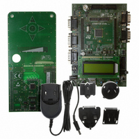
... Introduction The STM8S touch sensing evaluation kit (STM8/128-EV/TS) provides a platform that introduces users to STMicroelectronics capacitive touch sensing firmware library. The kit contains an STM8S touch sensing (TS) evaluation daughterboard (STM8Sxxx-TS1) in addition to the STM8/128-EVAL board. The STM8S touch sensing evaluation daughterboard provides an evaluation platform for resistor-capacitor (RC) touch sensing technology for an implementation using 5 keys and one slider ...
Page 2
Contents Contents 1 Overview . . . . . . . . . . . . . . . . . . . . . . . . . . . . . . . . . . . . ...
Page 3
UM0671 1 Overview This solution enables designers, comfortable with the use of standard microcontrollers, to create higher-end “look and feel” user interfaces by replacing conventional electro- mechanical switches with touch sensing controls. Designers can combine touch sensing functions with traditional ...
Page 4
... Getting started with the touch sensing evaluation kit 2 Getting started with the touch sensing evaluation kit 2.1 Evaluation kit contents The STM8S touch sensing evaluation kit (STM8/128-EV/TS) contains: STM8S touch sensing evaluation daughterboard (STM8Sxxx-TS1) STM8/128-EVAL board AC/DC power supply and its AC adaptors MCU selection guide ...
Page 5
UM0671 2.3 User interface The joystick is the main user interface used to display keys values and state or to modify the main touch sensing library parameters: de-bounce filter, detection time-out, low power mode, DES setting, etc. Note: The 5 ...
Page 6
Getting started with the touch sensing evaluation kit Display options Use the joystick to navigate through the sub-menus as shown in 1. Display the state of keys (K1, K2, K3, K4 and K5) and slider on the same screen. 2. ...
Page 7
... UM0671 3 Evaluation kit board settings 3.1 STM8S touch sensing daughterboard Figure 4. STM8S TS daughterboard overview 1 selection key Connectors to STM8/128-EVAL board I2C connector I measurement DD STM8S MCU This board uses a STM8S microcontroller (STM8S207K6T6C 32-pin LQFP package. Keys The 5 touchkeys (electrodes) are made of a simple copper surface. ...
Page 8
Evaluation kit board settings Slider The slider consists of 5 elementary juxtaposed electrodes. Analysis connectors All electrode and driven shield signals are available through two connectors (J2 and J3) for analysis and monitoring communication connector 2 In ...
Page 9
UM0671 Table 1. Daughterboard MCU pin description (continued) Pin no. Pin name 4 VSS 5 VCAP 6 VDD 7 VDDIO_1 8 PF4 9 VDDA 10 VSSA 11 PB5 12 PB4 13 PB3 14 PB2 15 PB1 16 PB0 17 PE5 ...
Page 10
... Evaluation kit board settings Table 2. Daughter/motherboard CN1 and CN5 header connections Motherboard connector (STM8/128-EVAL board) PI6 PG7 PC3 PE5 PE7 PD7 RESET# PA2 PA4 PA6 P H PH3 PF6 PF5 PF3 PF1 PB7 PB4 PB2 PB0 10/23 CN1 header PI7 1 2 PE0 ...
Page 11
... SWIM connector (top view) Table 4. SWIM connector pin description Pin number 1 VDD 3 GND Note: The SWIM connector of the STM8/128-EVAL board cannot be used. ) can be measured by removing jumper W2. DD Uses STM8S TS daughterboard SWIM connector (default setting) Connect PD1of STM8S TS daughterboard device to resource of STM8S/128- EVAL board ...
Page 12
Evaluation kit board settings 3.1.5 Analysis connectors (J2 and J3) Application designers can use connectors J2 and J3 to analyze electrode and driven shield signals on the daughterboard. Note: The user should take into account possible probe capacitance disturbance and ...
Page 13
... On STM8S TS daughterboard, connect both pins on jumper W2 – On STM8/128-EVAL board, set jumper JP3 as shown in daughterboard must have not its own power supply connected.) For more information about the STM8/128-EVAL board, please refer to UM0482: STM8/128- EVAL evaluation board user manual. LCD display Reset ...
Page 14
... Evaluation kit board settings Table 8. STM8/128-EVAL board settings Jumper Set to “STice” to keep motherboard MCU Reset pin low to enable JP1 correct TS daughterboard MCU functionality. (Default configuration) Connect both PSU and DTB jumpers to supply power supply the TS JP3 daughterboard. (Default configuration) 14/23 ...
Page 15
UM0671 4 Advanced evaluation using a debugging environment 4.1 Running the evaluation firmware in debug mode Designers can easily run the evaluation firmware in Debug mode using ST debugging and programming tools. Hardware tools to be ordered separately: – Raisonance ...
Page 16
Advanced evaluation using a debugging environment Figure 8. RLink configuration jumpers Figure 9. RLink USB and SWIM configuration 6. Download the STM8 touch sensing library from www.st.com/touch-sense-sw-lib 7. Launch the ST Visual Develop (STVD) integrated development environment. 8. Load the ...
Page 17
UM0671 Figure 10. Loading the TS evaluation firmware 9. In the “Project” menu, select “Setting” to define the C cosmic location directory (Figure 11). Figure 11. Project settings 10. Build the project by compiling and linking all the source code. ...
Page 18
Advanced evaluation using a debugging environment Figure 12. Building the project 11. Select RLink as the debugging tool. – In the “Debug instrument” menu, click “Target setting” and select “SWIM RLink” as shown in Figure 13. Debug instrument settings 12. ...
Page 19
UM0671 Figure 14. Debug mode Advanced evaluation using a debugging environment Doc ID 15330 Rev 4 19/23 ...
Page 20
Advanced evaluation using a debugging environment 4.3 Exploring key structures All key and slider data structures can be monitored through the STVD watch window. The main “touch sensing” structures are “sSCKeyInfo” and “sMCKeyInfo”. To learn more about library variables and ...
Page 21
... R28 1M_1%_0603 0R_0603/DNF R31 10K_1%_0603 R33 PC2 R30 1M_1%_0603 0R_0603/DNF R34 10K_1%_0603 R35 PC1 R32 1M_1%_0603 0R_0603/DNF 10K_1%_0603 STMicroelectronics STM8SxxxK-TS1 Daughter Board Title: Microcontrollers Division 190, avenue Célestin COQ Size: A4 Reference: MB836 Revision: C-01 13106 ROUSSET Cedex Date: 06-Nov-09 Sheet FRANCE ...
Page 22
... Revision 1 Initial release. Updated Figure 3: Navigation scheme on page page 6. Corrected reference to STM8S touch sensing evaluation kit from 3 “STM8/128-EVAL/TS” to “STM8/128-EV/TS”. 4 Updated values of C3 and C9 in Doc ID 15330 Rev 4 UM0671 Changes and Display options Figure 16 on page 21. ...
Page 23
... UM0671 Information in this document is provided solely in connection with ST products. STMicroelectronics NV and its subsidiaries (“ST”) reserve the right to make changes, corrections, modifications or improvements, to this document, and the products and services described herein at any time, without notice. All ST products are sold pursuant to ST’s terms and conditions of sale. ...