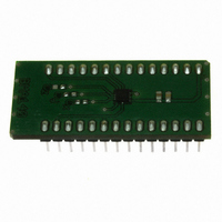
BMA140-SHUTL Bosch Sensortec, BMA140-SHUTL Datasheet - Page 10

BMA140-SHUTL
Manufacturer Part Number
BMA140-SHUTL
Description
BMA140 DAUGHTERCARD FOR DEV KIT
Manufacturer
Bosch Sensortec
Specifications of BMA140-SHUTL
Sensor Type
Accelerometer, 3 Axis
Sensing Range
±2g, 4g, 8g
Interface
Analog
Sensitivity
0.300 V/g
Voltage - Supply
1.8 V ~ 3.5 V
Embedded
No
Utilized Ic / Part
BMA140
For Use With
DM240021 - KIT STARTER MPLAB FOR PIC24H
Lead Free Status / RoHS Status
Contains lead / RoHS non-compliant
Other names
828-1010
4
4.1
An internal power-on reset (POR) is implemented to ensure proper reset during power-up. The
POR is active during 100µs (typical value). For this application the power on sequence only
occurs when a battery or an external supply is connected to VDD. Normally GND is connected
first. There should be a coupling capacitor connected between VDD and GND as shown in
chapter 4.8. Low resistance connections are required between decoupling capacitor and sensor
pads (< 100Ohms).
4.2
Two operation modes can be selected: NORMAL and STAND-BY mode. The operation modes
are selected by setting SEL1 and SEL0 according to the table given below.
SEL.1
When stand-by mode is activated, all sensor electrodes are connected to Vss. No electrostatic
forces are generated to the electrodes. Power consumption is drastically reduced in this mode.
All blocks are disabled except some bias generation and power-on reset generation. This
feature enables ultra low power mode operation if the sensor module is turned into stand-by
mode e.g. between each acceleration measurement.
4.3
Using the channel multiplexer, it is possible to choose specific axis output signals on the AMUX
pin. This allows the user to connect the triaxial BMA140 to an economical single channel AD
converter without loss of axis information. The channel selection on AMUX is performed by
setting SEL.0 and SEL.1 according to the following table. By setting both, SEL.0 and SEL.1 to
1, the sensor module is set to stand-by mode.
Rev. 1.1
© Bosch Sensortec GmbH reserves all rights even in the event of industrial property rights. We reserve all rights of disposal such
as copying and passing on to third parties. BOSCH and the symbol are registered trademarks of Robert Bosch GmbH, Germany.
Note: Specifications within this document are subject to change without notice.
SEL.1
0
0
1
1
1
1
0
0
Operation
Power-on reset and power-up sequence
Operation mode selection
Channel multiplexer output selection
SEL.0
SEL.0
0
1
0
1
0
1
0
1
Operation
NORMAL
STAND-
STAND-BY
Operation
NORMAL
NORMAL
NORMAL
Mode
BY
Mode
performance
Operation
Triaxial, analog acceleration sensor
Output signal on channel multiplexer serial output pin (AMUX)
Ax, Ay, Az plus AMUX = Ax
Ax, Ay, Az plus AMUX = Ay
Ax, Ay, Az plus AMUX = Az
Sensor module set to stand-by mode, no signal on X, Y, Z and AMUX
feature
current
saving
full
Data sheet
Consumption
Page 10
BMA140
Current
(typical)
(typical)
200 µA
0.7 µA
Description
Acceleration measurements of all axes
(Ax, Ay, Az plus AMUX) are performed.
All sensor features are enabled.
Acceleration measurements are stopped,
Ax, Ay, Az and AMUX signals are driven
to GND through 110kΩ resistors.
Bosch Sensortec
04 April 2008


