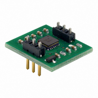
28026 Parallax Inc, 28026 Datasheet - Page 2

28026
Manufacturer Part Number
28026
Description
MODULE ACCEL HITACHI H48C 3-AXIS
Manufacturer
Parallax Inc
Datasheet
1.28026.pdf
(6 pages)
Specifications of 28026
Sensor Type
Accelerometer, 3 Axis
Sensing Range
±3g
Interface
Analog
Sensitivity
333 mV/g
Voltage - Supply
2.2 V ~ 3.6 V
Embedded
No
Utilized Ic / Part
BASIC Stamp® 2 Module
Product
Microcontroller Accessories
Data Bus Width
12 bit
Core Processor
MCP3204
Interface Type
Serial
Operating Supply Voltage
5 V
Board Size
20.3 mm x 17.8 mm
Lead Free Status / RoHS Status
Lead free / RoHS Compliant
Lead Free Status / RoHS Status
Lead free / RoHS Compliant, Lead free / RoHS Compliant
Other names
28026PAR
Available stocks
Company
Part Number
Manufacturer
Quantity
Price
Company:
Part Number:
280261-2
Manufacturer:
TE
Quantity:
20 000
Essential Connections
Connecting the H48C module to the BASIC Stamp 2 controller is a straightforward operation, requiring
just three I/O pins (the CLK and DIO pins may be shared in systems requiring the use of more than one
H48C module). See Figure 1 for connection details.
How It Works
Through MEMS (Micro Electro-Mechanical System) technology and built-in compensation, the H48C
accelerometer provides simultaneous outputs through analog conditioning circuitry to an MCP3204 ADC.
To "read" g-force of a given axis we actually read the voltage output from that axis and calculate g-force
using this formula:
In the formula,
from a 12-bit ADC channel, 3.3 is the H48C supply voltage, and 0.3663 is the H48C output voltage for 1g
(when operating at 3.3v). In practice this can be simplified to:
Using the BASIC Stamp 2 module as a host controller, we should multiply the 0.0022 by 100 (to 0.22) to
express the result in units of 0.01g. Using the ** operator, we are able to multiply by 0.22 and convert
the raw readings to g-force with this bit of code:
Note the IF-THEN structure which prevents a negative number from being divided – this is illegal in
PBASIC 2.x and will not return the correct result. By restructuring the conversion equation for negative
g-forces we can indeed arrive at the correct value. The output value,
In application the analog signal conditioning circuitry affects the rate at which readings can be taken
H48C module.
possible signal resolution into the ADC. By design, the filter circuit limits MC48C axis output rail-to-rail
rise/fall time to about five milliseconds.
IF (axCount >= rvCount) THEN
ELSE
ENDIF
Copyright© Parallax Inc. • Hitachi H48C 3-Axis Accelerometer Module (#28026) • 7/27/2007
gForce = (axCount - rvCount) ** GfCnv
gForce = -((rvCount - axCount) ** GfCnv)
axis
The filter/buffer circuit is designed to minimize noise while maintaining the highest
and
vRef
are expressed in counts from the ADC, 4095 is the maximum output count
G = ((axis – vRef) / 4095) x (3.3 / 0.3663)
Figure 1. H48C Connections
G = (axis – vRef) x 0.0022
Since MCP3204 has a significantly higher sample rate, the
' positive g-force
' negative g-force
gForce
, is a signed integer.
Rev 1.2
Page 2 of 6


