STEVAL-MKI047V1 STMicroelectronics, STEVAL-MKI047V1 Datasheet - Page 8
STEVAL-MKI047V1
Manufacturer Part Number
STEVAL-MKI047V1
Description
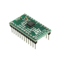
BOARD EVALUATION FOR LPR550AL
Manufacturer
STMicroelectronics
Series
MEMSr
Datasheets
1.STEVAL-MKI009V1.pdf
(42 pages)
2.STEVAL-MKI047V1.pdf
(12 pages)
3.STEVAL-MKI047V1.pdf
(4 pages)
Specifications of STEVAL-MKI047V1
Design Resources
STEVAL-MKI047V1 Schematic STEVAL-MKI047V1 Bill of Material STEVAL-MKI047V1 Gerber Files
Sensor Type
Gyroscope, 2 Axis
Sensing Range
±500°/sec
Interface
Analog
Sensitivity
2mV/°/s
Embedded
No
Utilized Ic / Part
LPY550AL
Lead Free Status / RoHS Status
Lead free by exemption / RoHS compliant by exemption
Voltage - Supply
-
Lead Free Status / Rohs Status
Lead free / RoHS Compliant
Other names
497-10047


Application hints
4
8/12
Application hints
Figure 3.
Power supply decoupling capacitors (100 nF ceramic or polyester + 10 µF Aluminum)
should be placed as near as possible to the device (common design practice).
The LPY550AL allows band limiting the output rate response through the use of an external
low pass filter (suggested) and/or high pass filter (optional) in addition to the embedded low
pass filter (f
4xOUTX and 4xOUTZ are respectively OUTX and OUTZ amplified outputs lines, internally
buffered to ensure low output impedance.
If external high pass or low pass filtering is not applied it is mandatory to short-circuit
respectively pad 4 to pad 5 and pad 9 to pad 10 when amplified outputs are used.
When only not-amplified outputs are used (OUTX/Z), it is suggested to set pads 5 and 9 to
fixed reference voltage (Vref).
When high pass filter is applied to not amplified output (OUTx), it is recommended to buffer
the line before entering ADC for performance optimization.
The LPY550AL IC includes a PLL (phase locked loop) circuit to synchronize driving and
sensing interfaces. Capacitors and resistors must be added at FILTVDD and VCONT pins
(as shown in
Typical values:
R1 = 1MOhm
C1 = 4.7 uF
R2 = 33kOhm
C2 = 2.2nF to 2.2uF
filtered output X
Not amplified
10kOhm
10nF
R1
t
LPY550AL electrical connections and external components values
= 140 Hz).
Figure
Recomended
Low-pass filter
C2
GND
C1
C2
3) to implement a low-pass filter.
470nF
R2
Optional
High-pass filter
Vref
R1
Doc ID 15808 Rev 2
C1
GND
GND
100 nF
1
5
GND
10 µF
LPY550AL
(Top View)
16
6
Vdd
14
8
13
9
C1
R1
Vref
ST
HP
PD
(TOP VIEW)
DIRECTION OF THE
DETECTABLE
ANGULAR RATES
R2
C2
GND
+ Ω
filtered output Z
Not amplified
LPY550AL
z
+ Ω
x
Related parts for STEVAL-MKI047V1
Image
Part Number
Description
Manufacturer
Datasheet
Request
R

Part Number:
Description:
BOARD EVAL FOR MEMS SENSORS
Manufacturer:
STMicroelectronics
Datasheet:

Part Number:
Description:
EVALBOARD/STEVAL-ISV014V1
Manufacturer:
STMicroelectronics
Part Number:
Description:
BOARD EVAL FOR ST802RT1
Manufacturer:
STMicroelectronics
Datasheet:

Part Number:
Description:
BOARD EVAL FOR VACUUM CLEANER
Manufacturer:
STMicroelectronics
Datasheet:

Part Number:
Description:
KIT DEV STARTER ST10F276Z5
Manufacturer:
STMicroelectronics
Datasheet:

Part Number:
Description:
BOARD LED CTLR/DVR STLED316S
Manufacturer:
STMicroelectronics
Datasheet:

Part Number:
Description:
BOARD EVAL BLDC SENSORLESS MOTOR
Manufacturer:
STMicroelectronics
Datasheet:

Part Number:
Description:
BOARD ELECT FISCAL CASH REGISTER
Manufacturer:
STMicroelectronics
Datasheet:

Part Number:
Description:
BOARD EVAL BIPO SOLUTION FOR PFC
Manufacturer:
STMicroelectronics
Datasheet:

Part Number:
Description:
BOARD EVAL UPS 450W VOUT=220V
Manufacturer:
STMicroelectronics
Datasheet:
Part Number:
Description:
STMicroelectronics [RIPPLE-CARRY BINARY COUNTER/DIVIDERS]
Manufacturer:
STMicroelectronics
Datasheet:
Part Number:
Description:
STMicroelectronics [LIQUID-CRYSTAL DISPLAY DRIVERS]
Manufacturer:
STMicroelectronics
Datasheet:
Part Number:
Description:
BOARD EVAL FOR MEMS SENSORS
Manufacturer:
STMicroelectronics
Datasheet: