AS5030 AB austriamicrosystems, AS5030 AB Datasheet - Page 5
AS5030 AB
Manufacturer Part Number
AS5030 AB
Description
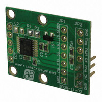
BOARD ADAPTER AS5030
Manufacturer
austriamicrosystems
Specifications of AS5030 AB
Sensor Type
Magnetic, Rotary Position
Sensing Range
360°
Interface
Serial
Voltage - Supply
5V
Embedded
No
Utilized Ic / Part
AS5030
Lead Free Status / RoHS Status
Lead free by exemption / RoHS compliant by exemption
Sensitivity
-


AS5030 8-bit Programmable Magnetic Rotary Encoder
Adapterboard Operation Manual
5 Using the serial interface with MCU
The most complete and accurate solution for a MCU to read the angle of a magnet is the serial interface.
The 8 bit value of the angle will be directly read, and some other indicators as AGC value or alarm bits can be read at the
same time.
Serial commands can be sent to the AS5030 as well, like the low power mode, lock AGC or reset.
Note: The MCU must have 5V I/O connected to the AS5030 adapter board, the AS5030 is a 5V device.
The connection between the MCU and the adapter board can be made with 2, 3 or 4 wires.
5.1
Jumper configuration: P1 close, P2 open.
By opening P2, the AS5030 is configured to 2-wire data
transmission mode.
Only Clock (CLK) and Data (DIO) signals are required. A
Chip Select (CS) signal is automatically generated by the
DX output, when a time-out of CLK occurs (typ. 20μs).
See AS5030 datasheet chapter 4.15.
Revision 1.0, 26.February 2009
Figure 7: Bidirectional serial connection (2 wire)
2-wire serial interface
www.austriamicrosystems.com
5.2
Jumper configuration: P1 and P2 close.
The MCU GPIO used for the DIO data signal should be
bi-directional: the MCU sends a 5 bit command first then
receives a 16 bit value on the same line. The DI input of
the adapter board must be connected to GND in this
mode.
The C source code for reading an angle with this
hardware configuration is described in Chapter 7.
Figure 8: Bidirectional serial connection (3 wire)
3-wire serial interface
Page 5 of 10
Related parts for AS5030 AB
Image
Part Number
Description
Manufacturer
Datasheet
Request
R

Part Number:
Description:
IC ENCODER ROTARY 8-BIT 16-TSSOP
Manufacturer:
austriamicrosystems
Datasheet:

Part Number:
Description:
BOARD DEMO AS5030
Manufacturer:
austriamicrosystems
Datasheet:
Part Number:
Description:
IC ENCODER ROTARY 8-BIT 16-TSSOP
Manufacturer:
austriamicrosystems
Datasheet:
Part Number:
Description:
8-bit High-speed Absolute Magnetic Rotary Encoder
Manufacturer:
austriamicrosystems
Datasheet:
Part Number:
Description:
IC SWITCH QUAD SPST 14-TSSOP
Manufacturer:
austriamicrosystems
Datasheet:
Part Number:
Description:
IC SWITCH QUAD SPST 14-TSSOP
Manufacturer:
austriamicrosystems
Datasheet:
Part Number:
Description:
IC AMP AUDIO MONO 1.8W 10-MSOP
Manufacturer:
austriamicrosystems
Datasheet:
Part Number:
Description:
IC AMP AUDIO MONO 1.8W 10-MSOP
Manufacturer:
austriamicrosystems
Datasheet:
Part Number:
Description:
IC AMP AUDIO MONO 1.8W 10-MSOP
Manufacturer:
austriamicrosystems
Datasheet:
Part Number:
Description:
IC AMP AUD 1.8W 3DB GAIN 10-MSOP
Manufacturer:
austriamicrosystems
Datasheet:
Part Number:
Description:
IC DRIVER LED 8-DIGIT 24-SOIC
Manufacturer:
austriamicrosystems
Datasheet:
Part Number:
Description:
IC DRIVER LED 8-DIGIT 24-SOIC
Manufacturer:
austriamicrosystems
Datasheet:
Part Number:
Description:
IC, LINE/SPEAKER PHONE CIRCUIT, SOIC-28
Manufacturer:
austriamicrosystems
Datasheet:
Part Number:
Description:
IC MULTI-STANDARD CMOS TELEPHONE SOIC-28
Manufacturer:
austriamicrosystems
Datasheet:
Part Number:
Description:
IC MULTI-STANDARD CMOS TELEPHONE SOIC-28
Manufacturer:
austriamicrosystems
Datasheet: