ATSTK500 Atmel, ATSTK500 Datasheet - Page 20
ATSTK500
Manufacturer Part Number
ATSTK500
Description
PROGRAMMER AVR STARTER KIT
Manufacturer
Atmel
Series
AVR®r
Type
MCUr
Specifications of ATSTK500
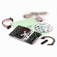
Contents
Board, Cable, CD and Documentation
Data Bus Width
8 bit
Interface Type
RS-232
For Use With/related Products
Atmel AVR Devices
For Use With
ATADAPCAN01 - EXTENSION CAN ADD-ON TO STK500/1
Lead Free Status / RoHS Status
Lead free / RoHS Compliant


1925C–AVR–3/03
Hardware Description
3-10
Table 3-2. AVR Sockets
Figure 3-16 shows an example of how AT90S2313 can be In-System Programmed. The
6-wire cable is connected from the ISP6PIN header to the red SPROG3 target ISP
header, and the AT90S2313 part is inserted in the red socket marked “SCKT3100D3”.
Figure 3-16. Example Connection for Programming AT90S2313
AVR Devices
AT90S1200
AT90S2313
AT90S2323
AT90S2343
ATtiny12
ATtiny22
ATtiny11
ATtiny28
AT90S4414
AT90S8515
ATmega161
AT90S4434
AT90S8535
ATmega16
ATmega163
ATmega323
AT90S2333
AT90S4433
ATmega8
ATtiny15
N/A
ATmega103
ATmega128
SCKT3300D3
AVR
STK500 Socket
SCKT3300D3
SCKT3400D1
SCKT3400D1
SCKT3500D-
SCKT3000D3
SCKT3100A3
SCKT3200A2
SCKT3600A1
SCKT3700A1
Use the STK501 Top Module
SPROG1
SPROG2
ISP6PIN
SPROG3
Color
Red
Blue
Blue
None
Red
Red
Green
Blue
Blue
Number
3
1
1
–
3
3
2
1
1
SPROG3
SPROG3
SPROG3
Target ISP Header
SPROG1. Connect RST on
PORTE to PB5 on PORTB.
Connect XTI on PORTE to PB3
(XTAL1 on 2323) on PORTB.
High-voltage Programming only
High-voltage Programming only
SPROG2
SPROG1. Connect RST on
PORTE to PB5 on PORTB.
Socket is not in use in this version
of STK500
AVR STK500 User Guide
Related parts for ATSTK500
Image
Part Number
Description
Manufacturer
Datasheet
Request
R

Part Number:
Description:
DEV KIT FOR AVR/AVR32
Manufacturer:
Atmel
Datasheet:

Part Number:
Description:
INTERVAL AND WIPE/WASH WIPER CONTROL IC WITH DELAY
Manufacturer:
ATMEL Corporation
Datasheet:
Part Number:
Description:
Low-Voltage Voice-Switched IC for Hands-Free Operation
Manufacturer:
ATMEL Corporation
Datasheet:
Part Number:
Description:
MONOLITHIC INTEGRATED FEATUREPHONE CIRCUIT
Manufacturer:
ATMEL Corporation
Datasheet:
Part Number:
Description:
AM-FM Receiver IC U4255BM-M
Manufacturer:
ATMEL Corporation
Datasheet:
Part Number:
Description:
Monolithic Integrated Feature Phone Circuit
Manufacturer:
ATMEL Corporation
Datasheet:
Part Number:
Description:
Multistandard Video-IF and Quasi Parallel Sound Processing
Manufacturer:
ATMEL Corporation
Datasheet:
Part Number:
Description:
High-performance EE PLD
Manufacturer:
ATMEL Corporation
Datasheet:
Part Number:
Description:
8-bit Flash Microcontroller
Manufacturer:
ATMEL Corporation
Datasheet:
Part Number:
Description:
2-Wire Serial EEPROM
Manufacturer:
ATMEL Corporation
Datasheet: