ATEVK1104 Atmel, ATEVK1104 Datasheet - Page 7
ATEVK1104
Manufacturer Part Number
ATEVK1104
Description
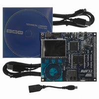
KIT DEV/EVAL FOR AVR32 AT32UC3A
Manufacturer
Atmel
Series
AVR®32r
Type
MCUr
Datasheets
1.ATAVRONE-PROBECBL.pdf
(16 pages)
2.ATEVK1104.pdf
(826 pages)
3.ATEVK1104.pdf
(90 pages)
4.ATEVK1104.pdf
(6 pages)
5.ATEVK1104.pdf
(12 pages)
Specifications of ATEVK1104
Contents
Evaluation Board, Software and Documentation
Processor To Be Evaluated
AT32UC3A3
Data Bus Width
32 bit
Interface Type
USB, SPI, USART
Silicon Manufacturer
Atmel
Core Architecture
AVR
Core Sub-architecture
AVR UC3
Silicon Core Number
AT32UC3A3256
Silicon Family Name
AVR
Kit Contents
Board CD Docs
Rohs Compliant
Yes
For Use With/related Products
AT32UC3A3
Lead Free Status / RoHS Status
Lead free / RoHS Compliant
Available stocks
Company
Part Number
Manufacturer
Quantity
Price
Company:

Part Number:
ATEVK1104
Manufacturer:
Atmel
Quantity:
135


3.6 Fast Fourier Transform
32138A-AVR32-02/10
In this application, we will apply the two basic filters, a high-pass and a low pass filter.
Applying the filters:
•
•
•
•
•
We will now have a closer look at the filters effect on the signal. By adjusting the
frequency of the input signals the filters will let more or less of the signal pass
through.
With an increase of frequency of a given signal, a low-pass filter will let less of it pass
through. By increasing the frequency of signal 2, it will be even less visible in the
output signal.
Higher frequency:
•
•
•
Lower frequency:
•
•
At 1 kHz, the remains of signal 2 are clearly visible in the output signal. By comparing
this to the known behavior called the frequency response of the filter, we see how our
observations match with the theory. At 1 kHz, called the filter’s cutoff frequency, the
noise is only reduced by 3 dB, which is equal to 50%.
FUN FACT: If we reduce the frequency of source 2 to approximately 433 Hz, signal 1
and 2 will have almost the same frequency. This will generate a vibrating volume
sound effect as signal 2 changes rapidly between amplifying and damping the output
signal. Experimenting with the frame rate and frequency of signal 2 will generate a
very visible and audible demo of this effect. The frequency of the vibration will be
equal to the difference in frequency between the two signals. This is most audible
when the difference is 4 Hz.
Fast Fourier transform (FFT) will extract the frequency components from a signal. The
theory behind this function is very complicated, but it provides a strikingly simple
output that can be very useful when analyzing the behavior of a digital signal
processing system.
Push and hold the BACK button for 3 seconds to reset the signals and filters.
Select the filter box and select the high-pass filter by pushing FUNC2.
Observe how the low frequency component of the output signal is reduced,
making the output very similar to signal 2.
Select the low-pass filter by pushing FUNC3.
Observe how the high frequency component of the output signal is reduced,
making the output very similar to signal 1.
Select signal source 2
Change the frequency to 5 kHz or more
Observe how the high frequency signal is clearly visible in the combined signal,
but not in the output signal
Select signal source 2 again
Reduce the frequency to about 1 khz
AVR329088
7
Related parts for ATEVK1104
Image
Part Number
Description
Manufacturer
Datasheet
Request
R

Part Number:
Description:
DEV KIT FOR AVR/AVR32
Manufacturer:
Atmel
Datasheet:

Part Number:
Description:
INTERVAL AND WIPE/WASH WIPER CONTROL IC WITH DELAY
Manufacturer:
ATMEL Corporation
Datasheet:
Part Number:
Description:
Low-Voltage Voice-Switched IC for Hands-Free Operation
Manufacturer:
ATMEL Corporation
Datasheet:
Part Number:
Description:
MONOLITHIC INTEGRATED FEATUREPHONE CIRCUIT
Manufacturer:
ATMEL Corporation
Datasheet:
Part Number:
Description:
AM-FM Receiver IC U4255BM-M
Manufacturer:
ATMEL Corporation
Datasheet:
Part Number:
Description:
Monolithic Integrated Feature Phone Circuit
Manufacturer:
ATMEL Corporation
Datasheet:
Part Number:
Description:
Multistandard Video-IF and Quasi Parallel Sound Processing
Manufacturer:
ATMEL Corporation
Datasheet:
Part Number:
Description:
High-performance EE PLD
Manufacturer:
ATMEL Corporation
Datasheet:
Part Number:
Description:
8-bit Flash Microcontroller
Manufacturer:
ATMEL Corporation
Datasheet:
Part Number:
Description:
2-Wire Serial EEPROM
Manufacturer:
ATMEL Corporation
Datasheet: