EFM32-G8XX-STK Energy Micro, EFM32-G8XX-STK Datasheet
EFM32-G8XX-STK
Specifications of EFM32-G8XX-STK
Available stocks


Related parts for EFM32-G8XX-STK


EFM32-G8XX-STK Summary of contents
Page 1
... Preliminary USER MANUAL Starter Kit EFM32-G8XX-STK Feature rich starter kit for evaluation, prototyping and application development for the EFM32 Gecko MCU family with the ARM Cortex-M3 CPU core. Main features; • Advanced Energy Monitoring provides real-time visibility into the energy consumption of an application or prototype design. ...
Page 2
... Advanced Energy Monitoring system for precise current tracking. • Special hardware configuration for isolation of the MCU power domain. • Full feature USB debugger with debug out functionality. • 160 segment Energy Micro LCD. • 20 pin expansion header. • Breakout pads for easy access to I/O pins. ...
Page 3
... STK block diagram An overview of the Kit is shown in the block diagram below. Figure 2.1. EFM32-G8XX-STK Block Diagram + 3V CR2032 Reset Debug In/ Out BC USB m ini B 2010-04-09 - REVISION Preliminary ...the world's most energy friendly microcontrollers Push buttons LEDs 50 Breakout pads 3 Touch slider 44 4 Touch Gecko ...
Page 4
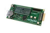
... Hardware layout The layout of the EFM32-G8XX-STK is shown below. Figure 3.1. EFM32-G8XX-STK hardware layout 2010-04-09 - REVISION Preliminary ...the world's most energy friendly microcontrollers 4 www.energymicro.com ...
Page 5
... Power supply 4.1 USB The EFM32-G8XX-STK can get its power from the standard USB mini port. The MCU voltage will be 3.15 volts when USB is connected. 4.2 Battery There is a socket for a 20mm coin cell battery, which can be used to power the kit. When the USB is disconnected and the battery connect switch is turned on, the EFM and its peripherals is powered by the battery ...
Page 6
Reset infrastructure 5.1 MCU The primary user reset for the MCU is the reset button on the MCU board. This will only reset the MCU. The MCU can also be reset by debuggers. 5.2 Board controller The board controller ...
Page 7
... LCD An Energy Micro LCD display is connected to the EFM. These lines are not shared on the breakout pads. Capacitors for the EFM32G LCD boost function is available on the EFM32-G8XX-STK. 6.4 Touch slider A touch slider utilizing the capacitive touch capability is available placed under the two push buttons on the kit, above the " ...
Page 8
... The AEM data is collected by the board controller and can be displayed application. For instance, the "Gecko commander" utility contains a "power" command which can dump power data to file. A GUI application for displaying power usage will be available for download from the Energy Micro download section later. ...
Page 9
Board controller The control MCU can act as a board controller (BC). There is a UART connection between the EFM and the BC. The connection is made by setting the bc_en line high. The EFM can then use the ...
Page 10
... Compared to the Energy Micro development kit, the functionality is limited. Unless you need/want some of the functions contained in the BSP, there is really no need to include or use it. The EFM32 in the Starter Kit can be fully usable without BSP support, and you can use all peripherals in the C:\Program Files\Energy Micro\EFM32 Gecko DK\boards\EFM32_Gxxx_STK\drivers folder without the BSP ...
Page 11
... STK_EnergyMode(uint8_t em); Informs the board controller about the Energy Mode (sleep mode) we are going into. This information can be used by the board controller to present a richer visual graph for illustrating what the EFM32 is currently doing. In addition to these main functions, full documentation of the complete API is included in the Doxygen/ HTML documentation of the installed package ...
Page 12
Connectors 10.1 Breakout pads Most I/O except the LCD pins are routed to the breakout pads at the top and bottom edge of the kit. A 2.54mm (100 mil) pitch pin header can be soldered in place on the ...
Page 13
Preliminary Table 10.2. Top breakout pad row Pin Alternative Functions 5V - PB9 - PB10 - GND - PB11 DAC_OUT0/LET0_O0 PB12 DAC_OUT1/LET0_O1 PB15 - GND - PD0 US1_TX/PCNT2_S0 PD1 TIM0_CC0/US1_RX/PCNT2_S1 PD2 TIM0_CC1/US1_CLK PD3 TIM0_CC2/US1_CS PD4 LEU0_TX PD5 LEU0_RX GND - ...
Page 14
Expansion header A 20 pin expansion header can be used to connect plugin boards. This contains a selection of I/O plus powers and ground. See the pinout in the table below. Table 10.3. Expansion header pinout I/O GND PC4 ...
Page 15
Debug connector This connector is used for Debug In and Debug Out (see Debug chapter). The pinout is described in the table. Table 10.4. Debug connector pinout Pin Function Note number 1 VTARGET Target voltage on the debugged application. ...
Page 16
... Debugging The EFM32-G8XX-STK has an on-board debugger, and it can be used in different ways to debug the EFM, both on and off kit. Below are descriptions on the different modes. Check the configuration chapter to find out how to change the debug setting. Table 11.1. Debug modes Mode Description Debug MCU In this mode the on-board debugger is connected to EFM on the EFM32-G8XX-STK ...
Page 17
... Kit. The following IDEs are supported. 12.1 IAR Embedded Workbench for ARM An evaluation version of IAR Embedded Workbench for ARM is included the EFM32-G8XX- STK package. Check the quick start guide for where to find updates, and IAR's own documentation on how to use it. You will find the IAR project file in the ...
Page 18
... Gecko Commander is a command line utility that comes with the Gecko DK Installer package. It can perform various kit and EFM32 specific tasks. Press "h" for help at the prompt for a listing of available commands. Press "h command" for help for a specific command, listing arguments and options. ...
Page 19
Version information The current version information can be read from Gecko Commander. Table 14.1. Current versions Type Firmware revision Hardware version 2010-04-09 - REVISION Preliminary ...the world's most energy friendly microcontrollers Version 1v0 1v0 19 Released 2010-04-09 2010-04-09 www.energymicro.com ...
Page 20
Schematic On the next pages you can find the schematic and the assembly drawings of the main board. 2010-04-09 - REVISION Preliminary ...the world's most energy friendly microcontrollers 20 www.energymicro.com ...
Page 21
... TOP TOP TOP Schematic Title Schematic Title Schematic Title EFM32 Starter Kit EFM32 Starter Kit EFM32 Starter Kit Page Title Page Title Page Title Title Page Title Page Title Page Designed: Designed: Designed: Approved: Approved: Approved <OrgAddr2> <OrgAddr2> <OrgAddr2> Document number ...
Page 22
... YELLOW YELLOW YELLOW YELLOW / / / TOP TOP TOP GND Schematic Title Schematic Title Schematic Title EFM32 Starter Kit EFM32 Starter Kit EFM32 Starter Kit Page Title Page Title Page Title User Interfaces User Interfaces User Interfaces Designed: Designed: Designed: Approved: Approved: Approved < ...
Page 23
... Path> <Schematic Path> <Schematic Path> TOP TOP TOP Schematic Title Schematic Title Schematic Title EFM32 Starter Kit EFM32 Starter Kit EFM32 Starter Kit Page Title Page Title Page Title Signal Assignments Signal Assignments Signal Assignments Designed: Designed: Designed: Approved: Approved: ...
Page 24
... C15 / TIMER0_CCC2 #1,3 / TIMER1_CC2 #0 / UART0_RX #3 / DBG_SWV #1 / ACMP1_CH7 <Schematic Path> <Schematic Path> <Schematic Path> TOP TOP TOP Schematic Title Schematic Title Schematic Title EFM32 Starter Kit EFM32 Starter Kit EFM32 Starter Kit Page Title Page Title Page Title EFM32 I/O EFM32 I/O EFM32 I/O Designed: Designed: Designed: ...
Page 25
... C414 22P 22P GND GND / / / TOP TOP TOP Schematic Title Schematic Title Schematic Title EFM32 Starter Kit EFM32 Starter Kit EFM32 Starter Kit Page Title Page Title Page Title EFM32 Power EFM32 Power EFM32 Power Designed: Designed: Designed: Approved: Approved: Approved < ...
Page 26
... LCD_PF[9.. <Schematic Path> <Schematic Path> <Schematic Path> TOP TOP TOP Schematic Title Schematic Title Schematic Title EFM32 Starter Kit EFM32 Starter Kit EFM32 Starter Kit Page Title Page Title Page Title LCD LCD LCD Designed: Designed: Designed: Approved: Approved: Approved: GB ...
Page 27
... Path> <Schematic Path> <Schematic Path> TOP TOP TOP Schematic Title Schematic Title Schematic Title EFM32 Starter Kit EFM32 Starter Kit EFM32 Starter Kit Page Title Page Title Page Title Power + Misc Power + Misc Power + Misc Designed: Designed: Designed: Approved: Approved: ...
Page 28
... TLV272 TLV272 / / / TOP TOP TOP Schematic Title Schematic Title Schematic Title EFM32 Starter Kit EFM32 Starter Kit EFM32 Starter Kit Page Title Page Title Page Title Advanced Energy Monitor Advanced Energy Monitor Advanced Energy Monitor Designed: Designed: Designed: Approved: Approved: Approved: ...
Page 29
... GND / / / TOP TOP TOP Schematic Title Schematic Title Schematic Title EFM32 Starter Kit EFM32 Starter Kit EFM32 Starter Kit Page Title Page Title Page Title Debug Interface Debug Interface Debug Interface Designed: Designed: Designed: Approved: Approved: Approved < ...
Page 30
... TOP TOP 10U 10U Schematic Title Schematic Title Schematic Title 100N 100N 100N 100N EFM32 Starter Kit EFM32 Starter Kit EFM32 Starter Kit GND Page Title Page Title Page Title Control MCU Control MCU Control MCU Designed: Designed: Designed: Approved: Approved: ...
Page 31
TP144 TP146 TP145 TP134 TP103 TP104 TP148 TP135 TP118 TP119 P600 D600 L600 R902 R904 LED902 U902 R901 R915 C913 R601 R903 R602 R905 R912 U600 LED901 U900 LED903 C600 C601 R703 R702 C911 R728 U701 X900 R909 C702 C703 ...
Page 32
P900 ...
Page 33
Preliminary Table of Contents 1. Introduction .............................................................................................................................................. 2 1.1. Features ....................................................................................................................................... 2 2. STK block diagram .................................................................................................................................... 3 3. Hardware layout ........................................................................................................................................ 4 4. Power supply ........................................................................................................................................... 5 4.1. USB ............................................................................................................................................. 5 4.2. Battery .......................................................................................................................................... 5 5. Reset infrastructure ................................................................................................................................... ...
Page 34
... Preliminary List of Figures 2.1. EFM32-G8XX-STK Block Diagram ............................................................................................................. 3 3.1. EFM32-G8XX-STK hardware layout ........................................................................................................... 4 2010-04-09 - REVISION ...the world's most energy friendly microcontrollers www.energymicro.com 35 ...
Page 35
Preliminary List of Tables 7.1. AEM accuracy ........................................................................................................................................ 8 10.1. Bottom breakout pad row ...................................................................................................................... 12 10.2. Top breakout pad row .......................................................................................................................... 13 10.3. Expansion header pinout ...................................................................................................................... 14 10.4. Debug connector pinout ........................................................................................................................ 15 11.1. Debug modes ..................................................................................................................................... 16 ...
Page 36
...