DM164123 Microchip Technology, DM164123 Datasheet
DM164123
Specifications of DM164123


Related parts for DM164123

DM164123 Summary of contents
Page 1
... PICDEM™ System Management © 2007 Microchip Technology Inc. USER’S GUIDE DS41304B ...
Page 2
... Select Mode, Smart Serial, SmartTel, Total Endurance, UNI/O, WiperLock and ZENA are trademarks of Microchip Technology Incorporated in the U.S.A. and other countries. SQTP is a service mark of Microchip Technology Incorporated in the U.S.A. All other trademarks mentioned herein are property of their respective companies. ...
Page 3
... Serial Communications does not appear to be working ............................ 19 3.2.2 Microcontroller does not run after programming using the MPLAB 3.2.3 The fan is not providing proper feedback .................................................. 19 3.2.4 Heating element is not heating .................................................................. 19 3.2.5 Temperature is not changing ..................................................................... 19 © 2007 Microchip Technology Inc. PICDEM™ SYSTEM MANAGEMENT Table of Contents 2 C™ ............................................................................................ 13 ® ...
Page 4
... PICDEM™ System Management User’s Guide Appendix A. Hardware Schematics A.1 Introduction .................................................................................................. 21 Appendix B. Register Maps B.1 Introduction .................................................................................................. 23 Worldwide Sales and Service .....................................................................................28 DS41304B-page iv © 2007 Microchip Technology Inc. ...
Page 5
... Chapter 3. “Troubleshooting” – This chapter provides resolutions for solving common problems associated with using the PICDEM System Management Board. • Appendix A. “Hardware Schematics” – Illustrates the PICDEM System Management Board hardware schematic diagram. © 2007 Microchip Technology Inc. PICDEM™ SYSTEM MANAGEMENT Preface NOTICE TO CUSTOMERS USER’S GUIDE ® ...
Page 6
... Optional arguments mcc18 [options] file [options] Choice of mutually exclusive errorlevel {0|1} arguments selection Replaces repeated text var_name [, var_name...] Represents code supplied by void main (void) user { ... } © 2007 Microchip Technology Inc. Examples ® IDE User’s Guide” ...
Page 7
... For the latest information on using other tools, read the tool-specific Readme files in the Readmes subdirectory of the MPLAB IDE installation directory. The Readme files contain updated information and known issues that may not be included in this user’s guide. © 2007 Microchip Technology Inc. Preface ™ System Management Board. ...
Page 8
... Programmers – The latest information on Microchip programmers. These include the MPLAB PM3 and PRO MATE Plus and PICkit DS41304B-page 4 ® II device programmers and the PICSTART ™ 2 development programmers. ® ® © 2007 Microchip Technology Inc. ...
Page 9
... Revision A (December 2006) • Initial release of this document. Revision B (January 2007) • Updated Chapter 1. • Updated Preface by adding the PICkit™ Serial Analyzer User Guide DS number. TROUBLESHOOTING See Chapter 3. “Troubleshooting” for information on common problems. © 2007 Microchip Technology Inc. Preface DS41304B-page 5 ...
Page 10
... PICDEM™ System Management User’s Guide NOTES: DS41304B-page 6 © 2007 Microchip Technology Inc. ...
Page 11
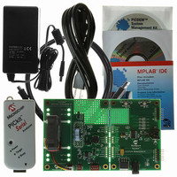
... PICkit™ Serial Analyzer CD-ROM 5. +12V power supply If you are missing any part of the kit, please contact your nearest Microchip sales office listed in the back of this publication for help. © 2007 Microchip Technology Inc. PICDEM™ SYSTEM MANAGEMENT System Management ™ ...
Page 12
... FIGURE 1-1: Temperature Sensor Three-Wire Fan Connector DS41304B-page 8 PICDEM™ SYSTEM MANAGEMENT BOARD Four-Wire Two-Wire Fan Connector Fan Connector TM TM PICkit 2 ICSP Connector TM PICkit Serial Analyzer Connector © 2007 Microchip Technology Inc. ...
Page 13
... The circuit has been designed so that the temperature range of the MCP9700 can be simulated. In order to simulate temperature with the potentiometer, the JP202 jumper must be set to the “POT” position. © 2007 Microchip Technology Inc. PICDEM™ System Management PICkit™ SERIAL ANALYZER PINOUT ...
Page 14
... Run the installation software for the PICDEM System Management GUI (D:\Setup\Setup.exe). 3. Run the System Management program (start <Programs<Microchip System Management Board). Within this screen there are several tabs that allow control and monitoring of various functions. DS41304B-page 10 WARNING © 2007 Microchip Technology Inc. ...
Page 15
... The ADC function provides Analog-to-Digital conversion of the voltage drop through potentiometer RP200. As you turn the potentiometer, the voltage indicator should change. Jumper JP202 must connect to the middle pin and the pin labeled “POT.” FIGURE 1-4: © 2007 Microchip Technology Inc. PICDEM™ System Management REAL-TIME CLOCK ANALOG-TO-DIGITAL CONVERTER (ADC) ...
Page 16
... The JP202 jumper can also be moved to con- nect the POT pin to the middle pin. This can allow the sweeping of temperatures in the full range of temperature values. FIGURE 1-6: DS41304B-page 12 SERIAL EEPROM THERMAL MANAGEMENT © 2007 Microchip Technology Inc. ...
Page 17
... The results will be shown on the screen to the left. See Appendix Table B-1 through Table B-4 for device address and word address details. FIGURE 1-7: © 2007 Microchip Technology Inc. PICDEM™ System Management Tab. A Read command can be executed by filling the “ ...
Page 18
... PICDEM™ System Management User’s Guide NOTES: DS41304B-page 14 © 2007 Microchip Technology Inc. ...
Page 19
... Low-speed PWM can be generated by PIC microcontrollers using the Enhanced Capture/Compare/PWM module. Speed can be measured with comparator and timer peripherals. © 2007 Microchip Technology Inc. PICDEM™ SYSTEM MANAGEMENT USER’S GUIDE 2 ...
Page 20
... PWM signal switches low, the Hall sensor output is no longer valid. Therefore, a technique called pulse stretching must be employed to ensure accurate measure- ments. Whenever a measurement is made, power must be provided to the fan for the duration of the measurement. (See figure below for more details.) FIGURE 2-2: DS41304B-page 16 THREE-WIRE PULSE STRETCHING © 2007 Microchip Technology Inc. ...
Page 21
... The tachometer line is the same as the three-wire fan, generating pulses based on the rotation of the permanent magnet of the fan; however, the Hall sensor is always on. Therefore, PWM stretching is not needed to ensure an accurate measurement. © 2007 Microchip Technology Inc. Background DS41304B-page 17 ...
Page 22
... PICDEM™ System Management User’s Guide NOTES: DS41304B-page 18 © 2007 Microchip Technology Inc. ...
Page 23
... Management Tab that the checkbox “Heater On” is checked. Check to ensure that the “Heater Enable” jumper JP200 is in place. 3.2.5 Temperature is not changing Check JP202 and ensure that it is connected to center pin and pin labeled MCP9700. © 2007 Microchip Technology Inc. PICDEM SYSTEM MANAGEMENT DC ® ICD 2 ® ...
Page 24
... PICDEM System Management NOTES: DS41304B-page 20 ® User’s Guide © 2007 Microchip Technology Inc. ...
Page 25
... Appendix A. Hardware Schematics A.1 INTRODUCTION This appendix contains the PICDEM™ System Management Board hardware diagrams. FIGURE A-1: SCHEMATIC SHEET 1 © 2007 Microchip Technology Inc. PICDEM™ SYSTEM MANAGEMENT USER’S GUIDE DS41304B-page 21 ...
Page 26
... PICDEM™ System Management User’s Guide FIGURE A-2: SCHEMATIC SHEET 2 DS41304B-page 22 © 2007 Microchip Technology Inc. ...
Page 27
... TABLE B-1: REG 0x00 0x01 0x02 0x03 0x04 0x05 0x06 0x07 0x08 0x09 0x0A 0x0B 0x0C 0x0D 0x0E 0x0F © 2007 Microchip Technology Inc. PICDEM™ SYSTEM MANAGEMENT REAL-TIME CLOCK CALENDAR: 0XA2 NAME CONFIG STOP – stop time function 0: RUN, 1: STOP CONFIG – ...
Page 28
... Lower Temperature Set Point Lower Temperature (degC) = [((Lower Temperature High Byte:Lower Temperature Low Byte) / 1023)) - .50] / .010 Frequency = 32768 / Tach Speed High Byte: Tach Speed Low Byte RPM = (Frequency / Bit <7:1> Bit 0 = Heating Element Enable (0 = Off On) DESCRIPTION © 2007 Microchip Technology Inc. ...
Page 29
... TABLE B-4: REG 0x00-0xFF © 2007 Microchip Technology Inc. SERIAL EEPROM: 0XA8 NAME Data EEPROM Data Byte Register Maps DESCRIPTION DS41304B-page 25 ...
Page 30
... PICDEM™ System Management User’s Guide NOTES: DS41304B-page 26 © 2007 Microchip Technology Inc. ...
Page 31
... PICDEM™ System Management User’s Guide NOTES: © 2007 Microchip Technology Inc. DS41304B-page 27 ...
Page 32
... Fax: 886-3-572-6459 Taiwan - Kaohsiung Tel: 886-7-536-4818 Fax: 886-7-536-4803 Taiwan - Taipei Tel: 886-2-2500-6610 Fax: 886-2-2508-0102 Thailand - Bangkok Tel: 66-2-694-1351 Fax: 66-2-694-1350 © 2007 Microchip Technology Inc. EUROPE Austria - Wels Tel: 43-7242-2244-39 Fax: 43-7242-2244-393 Denmark - Copenhagen Tel: 45-4450-2828 Fax: 45-4485-2829 France - Paris Tel: 33-1-69-53-63-20 ...