DM163014 Microchip Technology, DM163014 Datasheet - Page 22
DM163014
Manufacturer Part Number
DM163014
Description
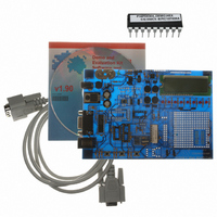
BOARD DEMO PICDEM4 12F629,16F630
Manufacturer
Microchip Technology
Type
MCUr
Specifications of DM163014
Contents
Board, Cable, CD
Processor To Be Evaluated
PIC18F1320 and PIC16F627A
Interface Type
RS-232
Silicon Manufacturer
Microchip
Silicon Core Number
PIC12F629, PIC12F675, PIC16F630, PIC16F676
Silicon Family Name
PIC12F, PIC16F And PIC18F
Kit Contents
PICDEM 4 PCB, MCU Samples, Cables, CD
Rohs Compliant
NA
Lead Free Status / RoHS Status
Lead free / RoHS Compliant
For Use With/related Products
PIC12F, PIC16F, PIC18F (8,14,18 pins)
Lead Free Status / Rohs Status
Lead free / RoHS Compliant
Other names
DM163014R
DM163014R
Q1543373
DM163014R
Q1543373
Available stocks
Company
Part Number
Manufacturer
Quantity
Price
Company:

Part Number:
DM163014
Manufacturer:
Microchip Technology
Quantity:
135


PICDEM 4 User’s Guide
A.13 REAL-TIME CLOCK
A.14 LCD DISPLAY
DS51337A-page 18
This circuit allows the user to configure a PICmicro MCU in either the U7 or U8 socket
for timekeeping, using a 32.768 kHz clock crystal connected to Timer1’s T1OSO and
T1OSI pins. ICD operation will not be functional when the Real-Time Clock circuit is
enabled. For RTC operation, these jumpers must be configured as follows:
• J7 - ON
• J9 - ON
• J21 - OFF
An LCD display with two lines, 16 characters per line, is connected to the I/O Expander
(U3), which can be driven by all three device sockets.
A 10K pot may be installed into R4 to adjust contrast on the LCD. If this is done, R5 and
R6 need to be removed.
The LCD is connected to the I/O Expander by three control lines (E, R/W, RS), and four
data lines (DB7:DB4). For LCD operation, these jumpers must be configured as
follows:
PIC16
• J8/10 - Upper two pins ON
• J21 - OFF (PORTB LEDs)
PIC18
• J8/10 - Lower two pins ON
• J21 - OFF (PORTB LEDs)
2003 Microchip Technology Inc.
Related parts for DM163014
Image
Part Number
Description
Manufacturer
Datasheet
Request
R

Part Number:
Description:
Manufacturer:
Microchip Technology Inc.
Datasheet:
Part Number:
Description:
Manufacturer:
Microchip Technology Inc.
Datasheet:
Part Number:
Description:
Manufacturer:
Microchip Technology Inc.
Datasheet:
Part Number:
Description:
Manufacturer:
Microchip Technology Inc.
Datasheet:
Part Number:
Description:
Manufacturer:
Microchip Technology Inc.
Datasheet:
Part Number:
Description:
Manufacturer:
Microchip Technology Inc.
Datasheet:
Part Number:
Description:
Manufacturer:
Microchip Technology Inc.
Datasheet:
Part Number:
Description:
Manufacturer:
Microchip Technology Inc.
Datasheet: