101-0552 Rabbit Semiconductor, 101-0552 Datasheet
101-0552
Specifications of 101-0552


Related parts for 101-0552


101-0552 Summary of contents
Page 1
RabbitCore RCM3200 C-Programmable Module with Ethernet User’s Manual 019–0118 • 080528–N ...
Page 2
... Rabbit, RabbitCore, and Dynamic C are registered trademarks of Digi International Inc. Rabbit 3000 is a trademark of Digi International Inc. The latest revision of this manual is available on the Rabbit Web site, www.rabbit.com, for free, unregistered download. Rabbit Semiconductor Inc. Trademarks www.rabbit.com RabbitCore RCM3200 ...
Page 3
Chapter 1. Introduction 1.1 RCM3200 Features ...............................................................................................................................2 1.2 Comparing the RCM3209/RCM3229 and RCM3200/RCM3220 ........................................................4 1.3 Advantages of the RCM3200 ...............................................................................................................5 1.4 Development and Evaluation Tools......................................................................................................6 1.4.1 RCM3200 Development Kit .........................................................................................................6 1.4.2 Software ........................................................................................................................................7 1.4.3 Connectivity Interface Kits ...........................................................................................................7 1.4.4 Online ...
Page 4
Memory .............................................................................................................................................. 36 4.5.1 SRAM......................................................................................................................................... 36 4.5.2 Flash EPROM............................................................................................................................. 36 4.5.3 Dynamic C BIOS Source Files................................................................................................... 36 Chapter 5. Software Reference 5.1 More About Dynamic C ..................................................................................................................... 37 5.2 Dynamic C Function Calls ................................................................................................................. 39 5.2.1 Digital I/O................................................................................................................................... 39 ...
Page 5
C.3 Keypad Labeling ................................................................................................................................86 C.4 Header Pinouts ...................................................................................................................................87 C.4.1 I/O Address Assignments...........................................................................................................87 C.5 Mounting LCD/Keypad Module on the Prototyping Board ..............................................................88 C.6 Bezel-Mount Installation....................................................................................................................89 C.6.1 Connect the LCD/Keypad Module to Your Prototyping Board.................................................91 C.7 LCD/Keypad Module Function Calls ................................................................................................92 C.7.1 ...
Page 6
RabbitCore RCM3200 ...
Page 7
The RCM3200 RabbitCore of embedded control systems. The RCM3200 features an inte- grated 10/100Base-T Ethernet port and provides for LAN and Internet-enabled systems to be built as easily as serial-communi- cation systems. Throughout this manual, the term RCM3200 refers to ...
Page 8
RCM3200 Features • Small size: 1.85" x 2.73" x 0.86" ( mm) • Microprocessor: Rabbit 3000 running at 44.2 MHz • (RCM3200 only) 10/100Base-T Ethernet port with supporting LEDs • 52 parallel 5 ...
Page 9
Table 1 below summarizes the main features of the RCM3200. Feature Rabbit 3000 running at Microprocessor Flash Memory Program Data SRAM Program Execution SRAM RJ-45 Ethernet Connector, Filter Capacitors, and LEDs 6 shared high-speed, CMOS-compatible ports: Serial Ports The RCM3210 ...
Page 10
Comparing the RCM3209/RCM3229 and RCM3200/RCM3220 We can no longer obtain certain components for the RCM3200/RCM3220 RabbitCore modules that support the originally specified -40°C to +70°C temperature range. Instead of changing the design of the RCM3200/RCM3220 RabbitCore modules to handle ...
Page 11
Advantages of the RCM3200 • Fast time to market using a fully engineered, “ready to run” microprocessor core. • Competitive pricing when compared with the alternative of purchasing and assembling individual components. • Easy C-language program development and debugging ...
Page 12
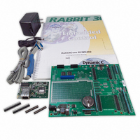
Development and Evaluation Tools 1.4.1 RCM3200 Development Kit The RCM3200 Development Kit contains the hardware you need to use your RCM3200 series RabbitCore module. • RCM3209 module. • Prototyping Board. • Universal AC adapter DC ...
Page 13
Software The RCM3200 and the RCM3220 are programmed using version 9.21 or later of Rabbit’s Dynamic C. A compatible version is included on the Development Kit CD-ROM. Dynamic C v. 9.60, which is required for the related RCM3209 and ...
Page 14
RabbitCore RCM3200 ...
Page 15
This chapter describes how to set up and connect an RCM3200 series module and the Prototyping Board included in the Development Kit. NOTE: This chapter (and this manual) assume that you have the RCM3200 Development Kit. If you purchased an ...
Page 16
Hardware Connections There are three steps to connecting the Prototyping Board for use with Dynamic C and the sample programs: 1. Attach the RCM3200 series RabbitCore module to the Prototyping Board. 2. Connect the programming cable between the RCM3200 ...
Page 17
Step 1 — Attach Module to Prototyping Board Turn the RCM3200 series module so that the Ethernet jack extends off the Prototyping Board, as shown in Figure 2 below. Align the pins from the headers on the bottom side ...
Page 18
Step 2 — Connect Programming Cable The programming cable connects the RCM3200 to the PC running Dynamic C to down- load programs and to monitor the RCM3200 module during debugging. 2.2.2.1 RCM3209 and RCM3229 Connect the 10-pin connector of ...
Page 19
... Figure 3(b). Connect Programming Cable to RCM3200 NOTE: Be sure to use the serial programming cable (part number 101-0542)—the pro- gramming cable has blue shrink wrap around the RS-232 converter section located in the middle of the cable. The USB programming cable and programming cables with red or clear shrink wrap from other Rabbit kits are not designed to work with RCM3200/RCM3220 modules ...
Page 20
Step 3 — Connect Power When all other connections have been made, you can connect power to the Prototyping Board. If you have the universal power supply, prepare the AC adapter for the country where it will be used ...
Page 21
Overseas Development Kits Development kits sold outside North America up to May, 2008, included a header connec- tor that may be connected to 3-pin header J9 on the Prototyping Board. The connector may be attached either way as long ...
Page 22
Starting Dynamic C NOTE: Dynamic later version is required if you are using an RCM3209 or an RCM3229 RabbitCore module. Once the RCM3200 is connected as described in the preceding pages, start Dynamic C ...
Page 23
If Dynamic C appears to compile the BIOS successfully, but you then receive a communi- cation error message when you compile and load the sample program possible that your PC cannot handle the higher program-loading baud rate. Try ...
Page 24
RabbitCore RCM3200 ...
Page 25
R To develop and debug programs for the RCM3200 (and for all other Rabbit hardware), you must install and use Dynamic C. 3.1 Introduction To help familiarize you with the RCM3200 modules, Dynamic C includes several sample programs. Loading, ...
Page 26
Sample Programs Of the many sample programs included with Dynamic C, several are specific to the RCM3200. Sample programs illustrating the general operation of the RCM3200, and serial communication are provided in the gram has comments that describe the ...
Page 27
Serial Communication The following sample programs can be found in the —This program demonstrates hardware flow control by configuring • FLOWCONTROL.C Serial Port C (PC3/PC2) for CTS/RTS with serial data coming from TxB at 115,200 bps. One character at ...
Page 28
SWITCHCHAR.C ASCII string on Serial Ports B and C. It also displays the serial data received from both ports in the window. STDIO To set up the Prototyping Board, you will ...
Page 29
Chapter 4 describes the hardware components and principal hardware subsystems of the RCM3200. Appendix A, “RCM3200 Specifica- tions,” provides complete physical and electrical specifications. Figure 5 shows these Rabbit-based subsystems designed into the RCM3200. User’s Manual 4. H ARDWARE Figure ...
Page 30
RCM3200 Digital Inputs and Outputs The RCM3200 has 52 parallel I/O lines grouped in seven 8-bit ports available on headers J1 and J2. The 44 bidirectional I/O lines are located on pins PA0–PA7, PB0, PB2–PB7, PD2–PD7, PE0–PE1, PE3–PE7, PF0–PF7, ...
Page 31
Figure 7 shows the use of the Rabbit 3000 microprocessor ports in the RCM3200 modules. Figure 7. Use of Rabbit 3000 Ports The ports on the Rabbit 3000 microprocessor used in the RCM3200 are configurable, and so the factory defaults ...
Page 32
Table 2. RCM3200 Pinout Configurations Pin Pin Name 1 GND 2 STATUS Output (Status) 3–10 PA[7:0] Parallel I/O 11 PF3 Input/Output 12 PF2 Input/Output 13 PF1 Input/Output 14 PF0 Input/Output 15 PC0 Output 16 PC1 Input 17 PC2 Output 18 ...
Page 33
Table 2. RCM3200 Pinout Configurations (continued) Pin Pin Name 1 /RES Reset output 2 PB0 Input/Output 3 PB2 Input/Output 4 PB3 Input/Output 5 PB4 Input/Output 6 PB5 Input/Output 7 PB6 Input/Output 8 PB7 Input/Output 9 PF4 Input/Output 10 PF5 Input/Output ...
Page 34
Table 2. RCM3200 Pinout Configurations (continued) Pin Pin Name 20 PG7 Input/Output 21 PG6 Input/Output 22 PG5 Input/Output 23 PG4 Input/Output 24 /IOWR Output 25 /IORD Output (0,0)—start executing at address zero (0,1)—cold boot from slave port (1,0)—cold boot from ...
Page 35
Memory I/O Interface The Rabbit 3000 address lines (A0–A19) and all the data lines (D0–D7) are routed inter- nally to the onboard flash memory and SRAM chips. I/0 write (/IOWR) and I/0 read (/IORD) are available for interfacing to ...
Page 36
Serial Communication The RCM3200 board does not have an RS-232 or an RS-485 transceiver directly on the board. However, an RS-232 or RS-485 interface may be incorporated on the board the RCM3200 is mounted on. For example, the Prototyping ...
Page 37
Ethernet Port (RCM3200 only) Figure 8 shows the pinout for the RJ-45 Ethernet port (J4). Note that some Ethernet con- nectors are numbered in reverse to the order used here. Figure 8. RJ-45 Ethernet Port Pinout Three LEDs are ...
Page 38
Serial Programming Port The RCM3200 serial programming port is accessed using header J3 or over an Ethernet connection via the RabbitLink EG2110. The programming port uses the Rabbit 3000’s Serial Port A for communication. Dynamic C uses the programming ...
Page 39
Serial Programming Cable The programming cable is used to connect the serial programming port of the RCM3200 serial COM port. The programming cable converts the RS-232 voltage levels used by the PC serial port to the ...
Page 40
A program “runs” in either mode, but can only be downloaded and debugged when the RCM3200 is in the Program Mode. Refer to the Rabbit 3000 Microprocessor User’s Manual gramming port. 4.3.2 Standalone Operation of the RCM3200 The RCM3200 must ...
Page 41
Other Hardware 4.4.1 Clock Doubler The RCM3200 takes advantage of the Rabbit 3000 microprocessor’s internal clock doubler. A built-in clock doubler allows half-frequency crystals to be used to reduce radiated emis- sions. The 44.2 MHz frequency specified for the ...
Page 42
Memory 4.5.1 SRAM The RCM3200 and the RCM3220 have 512K of program execution SRAM installed at U8. The RCM3200 and RCM3220 data SRAM installed 256K, and the RCM3210 has 128K data SRAM installed at U6.. 4.5.2 ...
Page 43
Dynamic integrated development system for writing embedded software. It runs on an IBM-compatible PC and is designed for use with Rabbit controllers and other controllers based on the Rabbit microprocessor. Chapter 4 provides the libraries and function ...
Page 44
Dynamic C release prior to v. 9.60 under Windows Vista. Programs can be downloaded at baud rates 460,800 bps after the program compiles. Dynamic C has a number of ...
Page 45
Dynamic C Function Calls 5.2.1 Digital I/O The RCM3200 was designed to interface with other systems, and so there are no drivers written specifically for the I/O. The general Dynamic C read and write functions allow you to customize ...
Page 46
Serial Communication Drivers Library files included with Dynamic C provide a full range of serial communications sup- port. The library provides a set of circular-buffer-based serial functions. The RS232.LIB library provides packet-based serial functions where packets can be delim- ...
Page 47
Board Initialization void brdInit (void); Call this function at the beginning of your program. This function initializes Parallel Ports A through G for use with the RCM3200 Prototyping Board. Summary of Initialization 1. I/O port pins are configured for ...
Page 48
Upgrading Dynamic C Dynamic C patches that focus on bug fixes are available from time to time. Check the Web site www.rabbit.com/support/ The default installation of a patch or bug fix is to install the file in a directory ...
Page 49
U 6.1 TCP/IP Connections Programming and development can be done with the RCM3200 RabbitCore modules without connecting the Ethernet port to a network. However, if you will be running the sample programs that use the Ethernet capability or will ...
Page 50
The following options require more care in address selection and testing actions, as conflicts with other users, servers and systems can occur: LAN — Connect the RCM3200’s Ethernet port to an existing LAN, preferably one to • which the development ...
Page 51
TCP/IP Primer on IP Addresses Obtaining IP addresses to interact over an existing, operating, network can involve a num- ber of complications, and must usually be done with cooperation from your ISP and/or network systems administrator. For this reason, ...
Page 52
T1 in Adapter Ethernet Typical Corporate Network If your system administrator can give you an Ethernet cable along with its IP address, the netmask and the gateway address, then you may be able to run the sample programs with- out ...
Page 53
IP Addresses Explained IP (Internet Protocol) addresses are expressed as 4 decimal numbers separated by periods, for example: 216.103.126.155 10.1.1.6 Each decimal number must be between 0 and 255. The total IP address is a 32-bit number consisting of ...
Page 54
How IP Addresses are Used The actual hardware connection via an Ethernet uses Ethernet adapter addresses (also called MAC addresses). These are 48-bit addresses and are unique for every Ethernet adapter manufactured. In order to send a packet to ...
Page 55
Dynamically Assigned Internet Addresses In many instances, there are no fixed IP addresses. This is the case when, for example, you are assigned an IP address dynamically by your dial-up Internet service provider (ISP) or when you have a ...
Page 56
Placing Your Device on the Network In many corporate settings, users are isolated from the Internet by a firewall and/or a proxy server. These devices attempt to secure the company from unauthorized network traffic, and usually work by disallowing ...
Page 57
Running TCP/IP Sample Programs We have provided a number of sample programs demonstrating various uses of TCP/IP for networking embedded systems. These programs require you to connect your PC and the RCM3200 board together on the same network. This ...
Page 58
How to Set IP Addresses in the Sample Programs With the introduction of Dynamic C 7.30 we have taken steps to make it easier to run many of our sample programs. Instead of the see a macro. This macro ...
Page 59
... IP address automatically.”) You may want to write down the existing values in case you have to restore them later not necessary to edit the gate- way address since the gateway is not used with direct connect. IP 10.10.6.101 Netmask 255.255.255.0 Direct Connection PC to RCM3200 Board 6 ...
Page 60
Run the PINGME.C Sample Program Connect the crossover cable from your computer’s Ethernet port to the RCM3200 board’s RJ-45 Ethernet connector. Open this sample program from the folder, compile the program, and start it running under Dynamic C. When ...
Page 61
ENET_MENU.C highlight bar on a graphic LCD display and to communicate it to another single-board computer via Ethernet. Use to program the other single-board computer with analog inputs ...
Page 62
RabbitCore RCM3200 ...
Page 63
A A. RCM3200 S PPENDIX Appendix A provides the specifications for the RCM3200, and describes the conformal coating. User’s Manual PECIFICATIONS 57 ...
Page 64
A.1 Electrical and Mechanical Characteristics Figure A-1 shows the mechanical dimensions for the RCM3200. Figure A-1. RCM3200 Dimensions NOTE: All measurements are in inches followed by millimeters enclosed in parentheses. All dimensions have a manufacturing tolerance of ±0.01" (0.25 mm). ...
Page 65
It is recommended that you allow for an “exclusion zone” of 0.04" (1 mm) around the RCM3200 in all directions (except above the RJ-45 plug) when the RCM3200 is incorpo- rated into an assembly that includes other printed circuit boards. ...
Page 66
Table A-1 lists the electrical, mechanical, and environmental specifications for the RCM3200. Table A-1. RabbitCore RCM3200 Specifications Feature Rabbit 3000 Microprocessor EMI Reduction Ethernet Port Flash Memory Data SRAM Program Execution SRAM Backup Battery General-Purpose I/O Additional Inputs Additional Outputs ...
Page 67
Table A-1. RabbitCore RCM3200 Specifications (continued) Feature Power Operating Temperature Humidity Connectors Board Size The RCM3210 was discontinued in July, 2004, and is no longer offered. * A.1.1 Headers The RCM3200 uses headers at J1 and J2 for physical connection ...
Page 68
A.1.2 Physical Mounting A 9/32” (7 mm) standoff with a 2-56 screw is recommended to attach the RCM3200 to a user board at the hole position shown in Figure A-3. Either use plastic hardware, or use insulating washers to keep ...
Page 69
A.2 Bus Loading You must pay careful attention to bus loading when designing an interface to the RCM3200. This section provides bus loading information for external devices. Table A-2 lists the capacitance for the various RCM3200 I/O ports. Table A-2. ...
Page 70
Figure A-4 shows a typical timing diagram for the Rabbit 3000 microprocessor external I/O read and write cycles. Figure A-4. I/O Read and Write Cycles—No Extra Wait States NOTE: /IOCSx can be programmed to be active low (default) or active ...
Page 71
Table A-4 lists the delays in gross memory access time for V Table A-4. Data and Clock Delays V Clock to Address Output Delay (ns) VDD 3.3 6 The measurements are taken at the 50% points ...
Page 72
A.3 Rabbit 3000 DC Characteristics Table A-5 outlines the DC characteristics for the Rabbit at 3.3 V over the recommended operating temperature range from T Table A-5. 3.3 Volt DC Characteristics Symbol Parameter I Input Leakage High IH Input Leakage ...
Page 73
A.4 I/O Buffer Sourcing and Sinking Limit Unless otherwise specified, the Rabbit I/O buffers are capable of sourcing and sinking 6 current per pin at full AC switching speed. Full AC switching assumes a 29.4 MHz CPU clock ...
Page 74
A.5 Conformal Coating The areas around the 32 kHz real-time clock crystal oscillator has had the Dow Corning silicone-based 1-2620 conformal coating applied. The conformally coated area is shown in Figure A-5. The conformal coating protects these high-impedance circuits from ...
Page 75
A.6 Jumper Configurations Figure A-6 shows the header locations used to configure the various RCM3200 options via jumpers. Figure A-6. Location of RCM3200 Configurable Positions Table A-7 lists the configuration options. Table A-7. RCM3200 Jumper Configurations Header Description JP1 External ...
Page 76
RabbitCore RCM3200 ...
Page 77
A PPENDIX Appendix B describes the features and accessories of the Proto- typing Board, and explains the use of the Prototyping Board to demonstrate the RCM3200 and to build prototypes of your own circuits. User’s Manual B. P ROTOTYPING B ...
Page 78
B.1 Introduction The Prototyping Board included in the Development Kit makes it easy to connect an RCM3200 module to a power supply and a PC workstation for development. It also pro- vides some basic I/O peripherals (switches and LEDs), as ...
Page 79
B.1.1 Prototyping Board Features —A power-supply jack and a 3-pin header are provided for con- Power Connection • nection to the power supply. Note that the 3-pin header is symmetrical, with both outer pins connected to ground and the center ...
Page 80
RS-232 serial port are available on the Prototyping RS-232 • Board. Refer to the Prototyping Board schematic (090-0137) for additional details. A 10-pin 0.1-inch spacing header strip is installed permit connection of ...
Page 81
B.2 Mechanical Dimensions and Layout Figure B-2 shows the mechanical dimensions and layout for the Prototyping Board. Figure B-2. RCM30/31/32XX Prototyping Board Dimensions NOTE: All measurements are in inches followed by millimeters enclosed in parentheses. All dimensions have a manufacturing ...
Page 82
Table B-1 lists the electrical, mechanical, and environmental specifications for the Proto- typing Board. Table B-1. Prototyping Board Specifications Parameter Board Size Operating Temperature Humidity Input Voltage Maximum Current Draw (including user-added circuits) Prototyping Area Standoffs/Spacers B.3 Power Supply The ...
Page 83
B.4 Using the Prototyping Board The Prototyping Board is actually both a demonstration board and a prototyping board demonstration board, it can be used to demonstrate the functionality of the RCM3200 right out of the box without any ...
Page 84
B.4.1 Adding Other Components There are pads that can be used for surface-mount prototyping involving SOIC devices. There is provision for seven 16-pin devices (six on one side, one on the other side). There are 10 sets of pads that ...
Page 85
B.4.3 Other Prototyping Board Modules and Options With the RCM3200 plugged into the ceiver, and can act as the “master” relative to another RabbitCore RCM3000, RCM3100, or RCM3200 plugged into the An optional LCD/keypad module is available that can be ...
Page 86
B.5 Use of Rabbit 3000 Parallel Ports Table B-2 lists the Rabbit 3000 parallel ports and their use for the RCM30/31/32XX Prototyping Board. Table B-2. RCM30/31/32XX Prototyping Board Use of Rabbit 3000 Parallel Ports Port I/O PA0–PA7 Output PB0–PB1 Input ...
Page 87
Table B-2. RCM30/31/32XX Prototyping Board Use of Rabbit 3000 Parallel Ports (continued) Port I/O PF0–PF7 Input PG0 Input PG1 Input PG2 Output PG3 Input PG4 Input PG5 Input PG6 Output PG7 Output User’s Manual Use Reserved for future use Switch ...
Page 88
RabbitCore RCM3200 ...
Page 89
A PPENDIX An optional LCD/keypad is available for the Prototyping Board. Appendix C describes the LCD/keypad and provides the soft- ware function calls to make full use of the LCD/keypad. C.1 Specifications Two optional LCD/keypad modules—with or without a panel-mounted ...
Page 90
Mounting hardware and (24") extension cable are also available for the LCD/key- pad module through your sales representative or authorized distributor. Table C-1 lists the electrical, mechanical, and environmental specifications for the LCD/ keypad module. Table C-1. ...
Page 91
C.2 Contrast Adjustments for All Boards Starting in 2005, LCD/keypad modules were factory-configured to optimize their contrast based on the voltage of the system they would be used in. Be sure to select a KDU5V LCD/keypad module for use with ...
Page 92
C.3 Keypad Labeling The keypad may be labeled according to your needs. A template is provided in Figure C-4 to allow you to design your own keypad label insert. To replace the keypad legend, remove the old legend and insert ...
Page 93
C.4 Header Pinouts Figure C-6 shows the pinouts for the LCD/keypad module. Figure C-6. LCD/Keypad Module Pinouts C.4.1 I/O Address Assignments The LCD and keypad on the LCD/keypad module are addressed by the /CS strobe as explained in Table C-2. ...
Page 94
C.5 Mounting LCD/Keypad Module on the Prototyping Board Install the LCD/keypad module on header sockets J7, J8, and J10 of the Prototyping Board as shown in Figure C-7. Be careful to align the pins over the headers, and do not ...
Page 95
C.6 Bezel-Mount Installation This section describes and illustrates how to bezel-mount the LCD/keypad module. Fol- low these steps for bezel-mount installation. 1. Cut mounting holes in the mounting panel in accordance with the recommended dimen- sions in Figure C-8, then ...
Page 96
Fasten the unit with the four 4-40 screws and washers included with the LCD/keypad module. If your panel is thick, use a 4-40 screw that is approximately 3/16" (5 mm) longer than the thickness of the panel. Figure C-9. ...
Page 97
C.6.1 Connect the LCD/Keypad Module to Your Prototyping Board The LCD/keypad module can be located as far as 2 ft. (60 cm) away from the RCM30/31/ 32XX Prototyping Board, and is connected via a ribbon cable as shown in Figure ...
Page 98
C.7 LCD/Keypad Module Function Calls When mounted on the Prototyping Board, the LCD/keypad module uses the external I/O bus on the Rabbit 3000 chip. Remember to add the line #define PORTA_AUX_IO to the beginning of any programs using the external ...
Page 99
C.7.3 LCD Display The functions used to control the LCD display are contained in the located in the Dynamic C DISPLAYS\GRAPHIC void glInit(void); Initializes the display devices, clears the screen. RETURN VALUE None. SEE ALSO glDispOnOFF, glBacklight, glSetContrast, glPlotDot, glBlock, ...
Page 100
Sets display contrast. NOTE: This function is not used with the LCD/keypad module since the support circuits are not available on the LCD/keypad module. void glFillScreen(char pattern); Fills the LCD display screen with a pattern. PARAMETER The ...
Page 101
Plots the outline of a polygon in the LCD page buffer, and on the LCD if the buffer is unlocked. Any portion of the polygon that is outside the LCD display area will be clipped. ...
Page 102
Fills a polygon in the LCD page buffer and on the LCD screen if the buffer is unlocked. Any portion of the polygon that is outside the LCD display area will be clipped. If fewer ...
Page 103
Draws a filled circle in the LCD page buffer and on the LCD if the buffer is unlocked. Any portion of the circle that is outside the LCD display area will be clipped. ...
Page 104
Puts an entry from the font table to the page buffer and on the LCD if the buffer is unlocked. Each font character's bitmap is column major and byte-aligned. Any portion ...
Page 105
Provides an interface between the STDIO string-formatting function will call this function, one character at a time, until the entire format- ted string has been parsed. Any portion of the bitmap ...
Page 106
Increments LCD screen locking counter. Graphic calls are recorded in the LCD memory buffer and are not transferred to the LCD if the counter is non-zero. NOTE: glBuffLock() sure to balance the calls not a requirement ...
Page 107
... LCD display area will be clipped. PARAMETERS x0 is the x coordinate of one endpoint of the line the y coordinate of one endpoint of the line the x coordinate of the other endpoint of the line the y coordinate of the other endpoint of the line. RETURN VALUE None. SEE ALSO glPlotDot, glPlotPolygon, glPlotCircle User’s Manual 101 ...
Page 108
Scrolls byte-aligned window left one pixel, right column is filled by current pixel type (color). PARAMETERS left is the top left corner of bitmap, must be evenly divisible by 8, otherwise ...
Page 109
Scrolls byte-aligned window down one pixel, top column is filled by current pixel type (color). PARAMETERS left is the top left corner of bitmap, must be evenly divisible by 8, otherwise ...
Page 110
Scrolls up or down, within the defined window by x number of pixels. The opposite edge of the scrolled window will be filled in with white pixels. The window ...
Page 111
Draws bitmap in the specified space. The data for the bitmap are stored in xmem. This function is like glXPutBitmap, except that it is faster. The restriction is ...
Page 112
TextGotoXY(windowFrame *window, int col, int row); Sets the cursor location on the display of where to display the next character. The display location is based on the height and width of the character to be displayed. NOTE: Execute the ...
Page 113
TextPrintf(struct windowFrame *window, char *fmt, ...); Prints a formatted string (much like printf) on the LCD screen. Only printable characters in the font set are printed, also escape sequences, '\r' and '\n' are recognized. All other escape sequences will ...
Page 114
C.7.4 Keypad The functions used to control the keypad are contained in the Dynamic C library. KEYPAD7.LIB void keyInit(void); Initializes keypad process RETURN VALUE None. SEE ALSO brdInit void keyConfig(char cRaw, char cPress, char cRelease, char cCntHold, char cSpdLo, char ...
Page 115
How many times to repeat after low speed repeat None. RETURN VALUE None. SEE ALSO keyProcess, keyGet, keypadDef void keyProcess(void); Scans and processes keypad data for key assignment, debouncing, press and release, ...
Page 116
Configures the physical layout of the keypad with the desired ASCII return key codes. Keypad physical mapping 1 × ['L'] ['U'] ['–'] where 'E' represents the ENTER key 'D' represents Down Scroll 'U' represents ...
Page 117
C.8 Sample Programs Sample programs illustrating the use of the LCD/keypad module with the Prototyping Board are provided in the SAMPLES\RCM3200 These sample programs use the external I/O bus on the Rabbit 3000 chip, and so the line is already ...
Page 118
RabbitCore RCM3200 ...
Page 119
A Appendix D provides information on the current requirements of the RCM3200, and includes some background on the chip select circuit used in power management. D.1 Power Supplies The RCM3200 requires a regulated 3.3 V ± 0. power ...
Page 120
The drain on the battery by the RCM3200 is typically 12 µA when no other power is sup- plied 165 mA·h battery is used, the battery can last almost 2 years: The actual life in your application will ...
Page 121
D.1.3 Reset Generator The RCM3200 uses a reset generator to reset the Rabbit 3000 microprocessor when the voltage drops below the voltage necessary for reliable operation. The reset occurs between 2.85 V and 3.00 V, typically 2.93 V. The RCM3200 ...
Page 122
RabbitCore RCM3200 ...
Page 123
PPENDIX The Prototyping Board has a header at J6 for a motor control option. While Rabbit does not support this option at this time, this appendix provides additional information about Parallel Port F on the Rabbit 3000 ...
Page 124
E.2 Header J6 The connector × 5, 0.1" pitch header suitable for connecting to an IDC header socket, with the following pin allocations. Table E-1. Prototyping Board Header J6 Pinout Pin Rabbit 3000 Primary Function 1 Parallel ...
Page 125
... Setting the bit to 0 configures that output as active high or low. Function Register—PFFR, address 00111101 (0x3D), Write-only, no default on reset. This register sets the alternate output function assigned to each of the pins of the port. ...
Page 126
... Upper nibble transfer clock is CLK/2 01 Upper nibble transfer clock is Timer A1 10 Upper nibble transfer clock is Timer B1 11 Upper nibble transfer clock is Timer B2 xx These bits are ignored PFFR 00111101 (0x3D) Value 0 Corresponding port bits function normally 1 Bit 0 carries SCLK_D 1 Bit 1 carries SCLK_C x No effect ...
Page 127
Table E-2. Parallel Port F Registers (continued) Register Name Port F Data Direction Register Bits 0:7 User’s Manual Mnemonic I/O Address PFDDR 00111111 (0x3F) Value 0 Corresponding port bit is an input 1 Corresponding port bit is an output R/W ...
Page 128
E.4 PWM Outputs The Pulse-Width Modulator consists of a 10-bit free-running counter and four width regis- ters. Each PWM output is high for counts out of the 1024-clock count cycle, where n is the value held in ...
Page 129
... PWM output High for single block. Spread PWM output throughout the cycle Address Address = 10001001 (0x89) Address = 10001011 (0x8B) Address = 10001101 (0x8D) Address = 10001111 (0x8F) Description The most significant eight bits for the Pulse-Width Modulator count are stored With a count of n, the PWM output will be high for n +1 clocks out of the 1024 clocks of the PWM counter ...
Page 130
E.6 Quadrature Decoder The two-channel Quadrature Decoder accepts inputs via Parallel Port F from two external optical incremental encoder modules. Each channel of the Quadrature Decoder accepts an in-phase (I) and a quadrature-phase (Q) signal, and provides 8-bit counters to ...
Page 131
The Quadrature Decoder generates an interrupt when the counter increments from 0x00 to 0x01 or when the counter decrements from 0x00 to 0xFF. Note that the status bits in the QDCSR are set coincident with the interrupt, and the interrupt ...
Page 132
... Quadrature Decoder interrupt use Interrupt Priority 1 1. Quadrature Decoder interrupt use Interrupt Priority 10 2. Quadrature Decoder interrupt use Interrupt Priority 11 3. QDC1R Address = 10010100 (0x94) (QDC2R) Address = 10010110 (0x96) Value The current value of the Quadrature Decoder read counter is reported. Address Description Description RabbitCore RCM3200 ...
Page 133
A additional information online documentation .......... 7 B battery backup battery life ....................... 114 circuit .............................. 114 external battery connec- tions ............................ 113 real-time clock ................ 114 reset generator ................. 115 use of battery-backed SRAM ....................................... 39 board initialization function ...
Page 134
... glDispOnOff ...............93 glDown1 ...................103 glFillCircle ..................97 glFillPolygon ..............96 glFillScreen .................94 glFillVPolygon ...........96 glFontCharAddr ..........97 glGetBrushType .......101 glGetPfStep .................98 glHScroll ...................103 glInit ...........................93 glLeft1 ......................102 glPlotCircle .................96 glPlotDot ...................101 glPlotLine .................101 glPlotPolygon .............95 glPlotVPolygon ..........95 glPrintf ........................99 glPutChar ....................99 glPutFont ....................98 glRight1 ....................102 glSetBrushType ........100 glSetContrast ..............94 glSetPfStep .................98 glSwap ......................100 glUp1 ........................102 glVScroll ...................104 glXFontInit .................97 glXPutBitmap ...........104 128 glXPutFastmap ...
Page 135
FLOWCONTROL.C ..... 21 PARITY.C .................... 21 SIMPLE3WIRE.C ........ 21 SIMPLE485MASTER.C 22 SIMPLE485SLAVE SIMPLE5WIRE.C ........ 21 SWITCHCHAR.C ........ 22 TCP/IP BROWSELED.C .......... 54 DISPLAY_MAC.C ....... 48 ECHOCLIENT.C .......... 54 ECHOSERVER.C ......... 54 ENET_AD.C ................. 54 ENET_MENU.C ........... ...
Page 136
RabbitCore RCM3200 ...
Page 137
RCM3200 Schematic www.rabbit.com/documentation/schemat/090-0152.pdf 090-0137 Prototyping Board Schematic www.rabbit.com/documentation/schemat/090-0137.pdf 090-0156 LCD/Keypad Module Schematic www.rabbit.com/documentation/schemat/090-0156.pdf 090-0128 Programming Cable Schematic www.rabbit.com/documentation/schemat/090-0128.pdf You may use the URL information provided above to access the latest schematics directly. User’s Manual S CHEMATICS 131 ...
Page 138
...