101-1243 Rabbit Semiconductor, 101-1243 Datasheet - Page 2
101-1243
Manufacturer Part Number
101-1243
Description
SECURE EMBEDDED WEB APPLICATIONS
Manufacturer
Rabbit Semiconductor
Series
RabbitCore 4000r
Type
MPU Moduler
Specifications of 101-1243
Contents
Prototype Board, Power Supply and Accessories
Interface Type
Ethernet
Operating Voltage
3.3 V
Board Size
47 mm x 72 mm x 21 mm
Product
Modules
For Use With/related Products
RCM4300
Lead Free Status / RoHS Status
Lead free / RoHS Compliant
Other names
316-1136


Hardware Setup
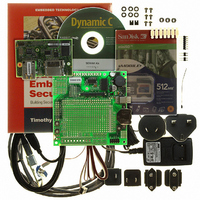
The Secure Embedded Web Application Kit 2.0 Getting Started instructions included with the Application
Kit show how to set up and program the RCM4300. Figure 1 summarizes the setup process.
Figure 1. Application Kit Setup
The following steps from the Secure Embedded Web Application Kit 2.0 Getting Started instructions list
the steps to place the RCM4300 RabbitCore module on the Prototyping Board once Dynamic C, the
Dynamic C software modules, and the software from the supplemental CD have been installed on your
computer.
Step 1 — Prepare the Prototyping Board
To facilitate handling the Prototyping Board, snap in four plastic standoffs to the four holes at the corners
from the bottom side of the Prototyping Board.
Step 2 — Insert the miniSD™ Card
Insert the miniSD™ Card.into the miniSD Card holder on the RCM4300. The card is designed to
fit easily only one way — do not bend the card or force it into the slot. While you insert the card,
take care to avoid touching the electrical contacts on the bottom of the card to prevent electrostatic
discharge damage to the card and to keep any moisture or other contaminants off the contacts.
You will sense a soft click once the card is inserted completely.
Step 3 — Attach RCM4300 Module to Prototyping Board
Turn the RCM4300 module so that the mounting holes line up with the corresponding holes on the Proto-
typing Board. Insert the metal standoffs, secure them from the bottom of the Prototyping Board using three
screws and washers, then insert the module’s header J4 on the bottom side into header socket RCM1 on
the Prototyping Board. (You may use plastic standoffs instead of the metal standoffs and screws.)
2
022-0127 Rev. A
Related parts for 101-1243
Image
Part Number
Description
Manufacturer
Datasheet
Request
R

Part Number:
Description:
COMPUTER SNGLBD BL2120 FRCTNLOCK
Manufacturer:
Rabbit Semiconductor
Datasheet:

Part Number:
Description:
KIT APPLCTN RABBITCORE RCM4010
Manufacturer:
Rabbit Semiconductor
Datasheet:

Part Number:
Description:
KIT MESH NETWORK ADD-ON RCM4510W
Manufacturer:
Rabbit Semiconductor
Datasheet:

Part Number:
Description:
KIT DEV FOR BL2500 COYOTE
Manufacturer:
Rabbit Semiconductor
Datasheet:

Part Number:
Description:
KIT APPLICATION SIMPLE SENSOR
Manufacturer:
Rabbit Semiconductor
Datasheet:

Part Number:
Description:
KIT DEV RABBITCORE RCM3750
Manufacturer:
Rabbit Semiconductor
Datasheet:

Part Number:
Description:
KIT DEV RABBIT 2000 INT'L
Manufacturer:
Rabbit Semiconductor
Datasheet:
Part Number:
Description:
KIT DEV RABBIT RCM2000 INT'L
Manufacturer:
Rabbit Semiconductor
Datasheet:

Part Number:
Description:
KIT DEVELOPMENT RCM3700 INT'L
Manufacturer:
Rabbit Semiconductor
Datasheet:
Part Number:
Description:
MODULE RABBITCORE RCM3720
Manufacturer:
Rabbit Semiconductor
Datasheet:
Part Number:
Description:
MODULE RABBITCORE RCM3220
Manufacturer:
Rabbit Semiconductor
Datasheet:
Part Number:
Description:
MODULE RABBITCORE RCM3210
Manufacturer:
Rabbit Semiconductor
Datasheet:
Part Number:
Description:
COMPUTER SGL-BOARD OP6600 W/SRAM
Manufacturer:
Rabbit Semiconductor
Datasheet:
Part Number:
Description:
COMPUTER SGL-BD BL2000 SRAM/FLSH
Manufacturer:
Rabbit Semiconductor