28138 Parallax Inc, 28138 Datasheet
28138
Specifications of 28138


Related parts for 28138


28138 Summary of contents
Page 1
... RS-232 DCE port with MAX232E transceiver 2 ® • DS1307 ( real-time-clock with 3v back-up battery (pre-installed) © Parallax, Inc. • Professional Development Board (#28138) • 06/2005 599 Menlo Drive, Suite 100 General: info@parallax.com Rocklin, California 95765, USA Technical: support@parallax.com Office: (916) 624-8333 Web Site: www.parallax.com Fax: (916) 624-8003 Educational: www ...
Page 2
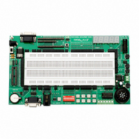
... A. 2.1 mm power connection (center positive VDC) B. Power switch C. BS1-IC, BS2-24, BS2-40, and Javelin Stamp sockets D. USB programming connection E. DB-9 (serial) programming connection F. BS1 Serial Adapter connection G. SX28AC/DP socket H. SX-Key programming connection 2 © Parallax, Inc. • Professional Development Board (#28138) • 06/2005 ...
Page 3
... The purpose of the VIN terminal is to provide +12 volts (the typical input voltage to the PDB) to external devices like relays, incandescent lamps, and stepper motors that are control via the L293D push-pull driver. © Parallax, Inc. • Professional Development Board (#28138) • 06/2005 ® products; is there anything else I’ll need? ...
Page 4
... Serial Adapter (#27111, available separately) or the original parallel port programming cable (requires DOS editor that is no longer supported). Note: The BS1-IC module may be used in conjunction with an installed SX28AC/DP micro. 4 Using 24-guage solid wire (also suggested for circuit DB-9 BS1-SA © Parallax, Inc. • Professional Development Board (#28138) • 06/2005 SX-Key ...
Page 5
... CAUTION: The SX28AC/DP micro must be removed before installing and using the BS2p40. Having both modules installed at the same time could cause an I/O pin conflict that could lead to damage to one or both of the modules. © Parallax, Inc. • Professional Development Board (#28138) • 06/2005 DB-9 BS1-SA ...
Page 6
... M10 M11 M12 M13 RB2 RB3 RB4 RB5 RC2 RC3 RC4 RC5 A10 A11 A12 A13 P10 P11 P12 P13 © Parallax, Inc. • Professional Development Board (#28138) • 06/2005 M14 M15 RB6 RB7 A6 A7 RC6 RC7 A14 A15 P14 P15 ...
Page 7
... Potentiometer (X5 and X6) Two 10 kΩ potentiometers are provided via X5 and X6. A 220 Ω series resistor is placed inline with the wiper connection to prevent an I/O pin from being connected directly to Vdd or Vss. © Parallax, Inc. • Professional Development Board (#28138) • 06/2005 7 ...
Page 8
... V+ terminal. When the enable inputs are high the outputs will follow the inputs, otherwise the outputs will Hi-Z state. See the L293D documentation (available separately) for additional details on use and configuration. 8 © Parallax, Inc. • Professional Development Board (#28138) • 06/2005 ...
Page 9
... The RJ-11 connector may be configured for both X-10 output and Maxim/Dallas 1-Wire I/O. For X-10 output when using a PL-513 or TW-523 interface, configure the RJ-11 port as follows (J2 in, J3 out): For 1-Wire I/O using a Blue Dot Receptor, configure the RJ-11 port as follows (J3 in, J2 out): © Parallax, Inc. • Professional Development Board (#28138) • 06/2005 9 ...
Page 10
... In addition to the SDA (serial data) and SCL (serial clock) connections, the SQW (programmable square wave output) is provided at X14 protocol which is directly supported by the © Parallax, Inc. • Professional Development Board (#28138) • 06/2005 The 2 C routines ...
Page 11
... Stamps In Class books • StampWorks • BASIC Stamp manual and online help file • Javelin Stamp manual • SX/B online help file • Nuts & Volts magazine “Stamp Applications” column (reprints) © Parallax, Inc. • Professional Development Board (#28138) • 06/2005 11 ...
Page 12
... PL-513 X-10 Powerline Interface 12 #BS1-IC #BS2-IC #BS2E-IC #BS2SX-IC #BS2P24-IC #BS2P40-IC #BS2PE-IC #BS2PX-IC #020-78267 #JS1-IC #SX28AC/DP #250-05060 #250-02060 #250-04050 #750-00007 #750-00008 #750-00008 #805-00006 #800-00003 #27111 #552-00007 #603-00006 #900-00005 #900-00008 #27976 #27977 #28015 #27964 #805-00004 #27940 © Parallax, Inc. • Professional Development Board (#28138) • 06/2005 ...