DEMO908GZ60E Freescale Semiconductor, DEMO908GZ60E Datasheet - Page 3
DEMO908GZ60E
Manufacturer Part Number
DEMO908GZ60E
Description
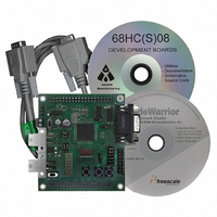
BOARD DEMO FOR 908GZ60 MCU
Manufacturer
Freescale Semiconductor
Series
HC08GRr
Type
MCUr
Specifications of DEMO908GZ60E
Design Resources
DEMO908GZ60E Schematic
Contents
Board, Cable, CD
Processor To Be Evaluated
908GZ
Data Bus Width
16 bit
Interface Type
RS-232
For Use With/related Products
68HC908GZ60
Lead Free Status / RoHS Status
Lead free / RoHS Compliant


Troubleshooting
Code will not run after reset
Unable to program the part using MON08 Monitor
Freescale Semiconductor
10. The “CPROG08SZ Programmer” window should close after the MCU Flash is programmed. You
11. Turn the RV1 dial (sometimes referred as a pot) and according to the position of the RV1 LED1
6. Click on “Debug” under Project in the menu bar or hit “F5.” The True-Time Simulator & Real-Time
7. If the “Attempting to contact target and pass security…” window appears, please make sure the
8. Click the “Contact target with these settings…” button and follow the instructions on the screen.
9. To cycle the power, you should use the PWR switch near the power terminal block (TB1). Click
•
•
•
•
•
Debugger interface window will appear. Please follow the instructions on the screen to complete
the Flash programming process.
following options are configured correctly:
–
–
–
–
When the “Erase and Program Flash?” window appears, click the “Yes” button.
“OK” in the “Power Cycle Dialog” window. Please follow the remaining instructions on the screen
to complete the Flash programming process.
are now ready to run the DEMO908GZ60_ATD code. Click on the green arrow in the toolbar at the
top of the screen to run the program. Once you click this button, a message in the command
window (bottom right-hand side) should say “RUNNING”.
through LED8 will be turned on and off.
Make sure the “MON_EN” and “VTST_EN” jumpers are removed and press reset again.
Reinstall the jumpers to the default position. Refer to figure 1.
Make sure the jumpers are in the debug position. Refer to figure 2.
Make sure the COM port matches the serial port in “Attempting to contact target and pass
security…” window.
Make sure the supply voltage connected to the terminal power block is +9 VDC.
Target Hardware Type: Class 3
Serial Port: 1 (Depends on the PC COM Port)
Baud: 7200 Baud
Target MCU Security bytes: Check the “IGNORE security failure and enter monitor mode”
checkbox
Figure 2. MON08 Debug Setting for Serial Connection
DEMO908GZ60 Quick Start Guide, Rev. 0.0
Troubleshooting
3
Related parts for DEMO908GZ60E
Image
Part Number
Description
Manufacturer
Datasheet
Request
R

Part Number:
Description:
Manufacturer:
Freescale Semiconductor, Inc
Datasheet:
Part Number:
Description:
Manufacturer:
Freescale Semiconductor, Inc
Datasheet:
Part Number:
Description:
Manufacturer:
Freescale Semiconductor, Inc
Datasheet:
Part Number:
Description:
Manufacturer:
Freescale Semiconductor, Inc
Datasheet:
Part Number:
Description:
Manufacturer:
Freescale Semiconductor, Inc
Datasheet:
Part Number:
Description:
Manufacturer:
Freescale Semiconductor, Inc
Datasheet:
Part Number:
Description:
Manufacturer:
Freescale Semiconductor, Inc
Datasheet:
Part Number:
Description:
Manufacturer:
Freescale Semiconductor, Inc
Datasheet:
Part Number:
Description:
Manufacturer:
Freescale Semiconductor, Inc
Datasheet:
Part Number:
Description:
Manufacturer:
Freescale Semiconductor, Inc
Datasheet:
Part Number:
Description:
Manufacturer:
Freescale Semiconductor, Inc
Datasheet:
Part Number:
Description:
Manufacturer:
Freescale Semiconductor, Inc
Datasheet:
Part Number:
Description:
Manufacturer:
Freescale Semiconductor, Inc
Datasheet:
Part Number:
Description:
Manufacturer:
Freescale Semiconductor, Inc
Datasheet:
Part Number:
Description:
Manufacturer:
Freescale Semiconductor, Inc
Datasheet: