DEMO9S08SE8 Freescale Semiconductor, DEMO9S08SE8 Datasheet
DEMO9S08SE8
Specifications of DEMO9S08SE8


Related parts for DEMO9S08SE8


DEMO9S08SE8 Summary of contents
Page 1
... DEMO9S08SE8 Demonstration Board for Freescale MC9S08SE8 Microcontroller USER GUIDE Email: Support: support@axman.com www.axman.com ...
Page 2
CAUTIONARY NOTES ..............................................................................................................4 TERMINOLOGY.........................................................................................................................4 FEATURES ................................................................................................................................5 REFERENCES ...........................................................................................................................6 GETTING STARTED..................................................................................................................6 SOFTWARE DEVELOPMENT ...................................................................................................6 MEMORY MAP ..........................................................................................................................6 DEVELOPMENT SUPPORT ......................................................................................................7 INTEGRATED ...
Page 3
Figure 1: BDM Port .....................................................................................................................7 Figure 2: PWR_SEL Option Header ...........................................................................................8 Figure 3. VX_EN Option Header ...............................................................................................9 Figure 4: OSC_EN ...
Page 4
... EMC Information on the DEMO9S08SE8 board: a) This product, as shipped from the factory with associated power supplies and cables, has been verified to meet with FCC requirements as a CLASS A product. ...
Page 5
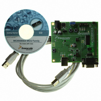
... The DEMO9S08SE8 is an evaluation or demonstration board for the MC9S08SE8 microcon- troller. Development of applications is quick and easy with the integrated USB-BDM, sample software tools, and examples. An optional BDM_PORT port is also provided to allow use of a BDM_PORT cable. A 40-pin connector allows connecting the DEMO9S08SE8 board to an ex- panded evaluation environment. • ...
Page 6
... NOTE: Accessing unimplemented memory locations causes an illegal-address reset. DEMO9S08SE8 User Guide (this document) DEMO9S08SE8 Board Schematic, Rev. C Direct Page Registers RAM Unimplemented High Page Registers Unimplemented FLASH ...
Page 7
... NOTE: This header is not installed in default configuration. POWER The DEMO9S08SE8 is designed to be powered from the USB_BDM during application devel- opment. A 2.0mm barrel connector has been applied to support stand-alone operation. In ad- dition, the board may be powered through connector J1. The board may also be configured to supply power through connector J1 to external circuitry ...
Page 8
When using the integrated USB-BDM, the board draws power from the USB bus. Total cur- rent consumption of the board ...
Page 9
The on-board voltage regulator (VR1) accepts power input through a 2.0mm barrel connector (PWR). Input voltage may range from +5V ...
Page 10
... Manual for details on configuring LVD operation. TIMING By default, the DEMO9S08SE8 uses timing provided from an internal 32 kHz frequency refer- ence and an internal frequency-locked loop (FLL). The FLL output is trimmable to ± 0.2% of nominal. Refer to the MC9S08SE8 Reference Manual for further details on clock operation. ...
Page 11
... MCU Port PTB1/KBIP5/TXD/ADP7 PTB0/KBIP4/RXD/ADP6 Virtual Serial Port The DEMO9S08SE8 provides a virtual serial port through the USB-BDM. Use of the virtual serial port requires the P&E Toolkit. The Toolkit is available on the DVD supplied with the demo board. COM_SEL The COM_SEL option header select between the virtual serial port implemented through the USB-BDM or the RS-232 PHY ...
Page 12
... GND 5 USER OPTIONS The DEMO9S08SE8 includes various input and output devices to aid application development. User I/O devices include 2 momentary pushbutton switches, 2 green LEDs, 1 potentiometer, and 1 phototransistor. Each device may be enabled or disabled individually by the USER_EN option header. Each user enable is clearly marked as to functionality. ...
Page 13
... Enable LED1 LED2 Enable LED2 RV1 Enable RV1 RZ1 Enable RZ1 I/O PORT CONNECTOR This port connector provides access to DEMO9S08SE8 I/O signals. Signal positions not shown listed are not connected on the board. Figure 6: MCU I/O Port Connector PTB1/KBIP5/TXD/ADP7 PTB0/KBIP4/RXD/ADP6 PTA2/KBIP2/ADP2 PTA3/KBIP3/ADP3 PTA0/KBIP0/TPM1CH0/ADP0 ...