DEMO9S08JS16 Freescale Semiconductor, DEMO9S08JS16 Datasheet - Page 15
DEMO9S08JS16
Manufacturer Part Number
DEMO9S08JS16
Description
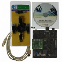
BOARD DEMO FOR JS16 FAMILY
Manufacturer
Freescale Semiconductor
Type
MCUr
Datasheets
1.DC9S08JS16.pdf
(49 pages)
2.DEMO9S08JS16.pdf
(32 pages)
3.DEMO9S08JS16.pdf
(8 pages)
4.DEMO9S08JS16.pdf
(8 pages)
5.DEMO9S08JS16.pdf
(4 pages)
Specifications of DEMO9S08JS16
Contents
2 Boards, Cable, Documentation, DVD
Processor To Be Evaluated
MC9S08JS16
Data Bus Width
8 bit
Interface Type
USB
Operating Supply Voltage
5 V
Silicon Manufacturer
Freescale
Core Architecture
HCS08
Core Sub-architecture
HCS08
Silicon Core Number
MC9S08
Silicon Family Name
S08JS
Rohs Compliant
Yes
For Use With/related Products
MC9S08JS16
Lead Free Status / RoHS Status
Lead free / RoHS Compliant


3.6
Freescale Semiconductor
1
2
3
4
5
6
Num
Typicals are measured at 25 °C. See
Values given here are preliminary estimates prior to completing characterization.
Most customers are expected to find that auto-wakeup from stop2 or stop3 can be used instead of the higher current wait
mode. Wait mode typical is 560 μA at 5 V and 422 μA at 3 V with f
Values given under the following conditions: low range operation (RANGE = 0), low power mode (HGO = 0).
Here USB module is enabled and clocked at 48 MHz (USBEN = 1, USBVREN =1, USBPHYEN = 1 and USBPU = 1), and
D+ and D– pulled down by two 15.1 kΩ resisters independently. The current consumption may be much higher when the
packets are being transmitted through the attached cable.
MCU enters stop3 mode, USB bus in idle state. The USB suspend current will be dominated by the D+ pullup resister.
1
2
3
4
5
6
7
8
9
Supply Current Characteristics
C
C
P
P
P
P
P
P
T
T
Run supply current
= 2 MHz, f
Run supply current
clock = 48 MHz, f
module on)
Stop2 mode supply current
Stop3 mode supply current, all module off
RTC adder to stop2 or stop3
LVD adder to stop3 (LVDE = LVDSE = 1)
Adder to stop3 for oscillator enabled
(ERCLKEN =1 and EREFSTEN = 1)
USB module enable current
USB suspend current
Bus
= 1 MHz, BLPE mode)
Bus
Parameter
3
3
measured at (CPU clock
measured at
= 24 MHz, PEE mode, all
6
MC9S08JS16 Series MCU Data Sheet, Rev. 4
Table 7. Supply Current Characteristics
Figure 12
5
3
, 25 °C
through
4
(CPU
Figure 10
Symbol
ΔI
ΔI
ΔI
ΔI
S2I
S3I
RI
RI
I
SUSP
SOSC
SRTC
USBE
SLVD
for typical curves across voltage/temperature.
Bus
DD
DD
DD
DD
= 1 MHz.
V
DD
5
3
5
3
5
3
5
3
5
3
5
3
5
3
5
5
(V)
Typical
19.93
18.74
106.7
273.3
1.03
0.83
1.36
1.18
1.50
1.31
95.6
300
300
5.6
5.3
1.5
1
Electrical Characteristics
Max
—
—
—
—
—
—
—
—
—
—
—
—
—
—
—
—
2
Unit
mA
mA
mA
μA
μA
μA
μA
nA
nA
μA
μA
μA
μA
μA
15
Related parts for DEMO9S08JS16
Image
Part Number
Description
Manufacturer
Datasheet
Request
R

Part Number:
Description:
Manufacturer:
Freescale Semiconductor, Inc
Datasheet:
Part Number:
Description:
Manufacturer:
Freescale Semiconductor, Inc
Datasheet:
Part Number:
Description:
Manufacturer:
Freescale Semiconductor, Inc
Datasheet:
Part Number:
Description:
Manufacturer:
Freescale Semiconductor, Inc
Datasheet:
Part Number:
Description:
Manufacturer:
Freescale Semiconductor, Inc
Datasheet:
Part Number:
Description:
Manufacturer:
Freescale Semiconductor, Inc
Datasheet:
Part Number:
Description:
Manufacturer:
Freescale Semiconductor, Inc
Datasheet:
Part Number:
Description:
Manufacturer:
Freescale Semiconductor, Inc
Datasheet:
Part Number:
Description:
Manufacturer:
Freescale Semiconductor, Inc
Datasheet:
Part Number:
Description:
Manufacturer:
Freescale Semiconductor, Inc
Datasheet:
Part Number:
Description:
Manufacturer:
Freescale Semiconductor, Inc
Datasheet:
Part Number:
Description:
Manufacturer:
Freescale Semiconductor, Inc
Datasheet:
Part Number:
Description:
Manufacturer:
Freescale Semiconductor, Inc
Datasheet:
Part Number:
Description:
Manufacturer:
Freescale Semiconductor, Inc
Datasheet:
Part Number:
Description:
Manufacturer:
Freescale Semiconductor, Inc
Datasheet: