DEMO9S08AW60E Freescale Semiconductor, DEMO9S08AW60E Datasheet - Page 3
DEMO9S08AW60E
Manufacturer Part Number
DEMO9S08AW60E
Description
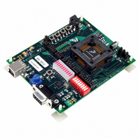
DEMO BOARD FOR MC9S08AW60
Manufacturer
Freescale Semiconductor
Type
MCUr
Datasheets
1.DEMO9S08AW60E.pdf
(24 pages)
2.DEMO9S08AW60E.pdf
(4 pages)
3.DEMO9S08AW60E.pdf
(5 pages)
Specifications of DEMO9S08AW60E
Contents
Board
Processor To Be Evaluated
MC9S08AW60
Interface Type
RS-232, USB
Silicon Manufacturer
Freescale
Core Architecture
HCS08
Core Sub-architecture
HCS08
Silicon Core Number
MC9S08
Silicon Family Name
S08AW
Rohs Compliant
Yes
For Use With/related Products
MC9S08AW60
Lead Free Status / RoHS Status
Contains lead / RoHS non-compliant


Freescale Semiconductor
4.
5.
6.
7.
8.
9.
10. In the "Port Settings" window, enter the following settings: Bits per second: 9600, Data
11. From within the Freescale CodeWarrior window, click on "Debug" under Project in the
12. When the ICD Connection Assistant appears, click the "Connect" button.
13. When the "Erase and Program Flash?" window appears, click the "Yes" button.
14. The "CPROGHCS08 Programmer" window should close after the MCU FLASH is
15. From the terminal window you set up in steps 7 through 10, you can type characters
16. Toggle dip switches 0-7 on SW5 to toggle LEDs 0-7 on the lightbar. Press SW1 when
17. Press SW2 and SW3 to see LEDs 0 and 1 on the lightbar light up. Press SW4 when
18. Values will be displayed in the terminal window based on the A to D input of the
19. Values will be displayed in the terminal window based on the amount of light sensed
Check the jumper settings and make sure they are in the default position. use Figure
1 as a guide.
Connect the USB cable, the USB, PWR_OUT, and VDD LEDs should be on.
Connect a serial cable to the PC and then to the board.
Open up a terminal window from within Windows XP by clicking on Start --> All
Programs --> Accessories --> Communications --> HyperTerminal
Give your terminal connection a name (such as DEOM9S08AW60_APP) and click the
"OK" button.
In the "Connect using" pulldown, select the COM port you connected your serial cable
to, and click the "OK" button.
bits: 8, Parity: None, Stop bits: 1, Flow control: None. Click the "OK" button.
menu bar or press "F5". The True-Time Simulator& Real-Time Debugger interface
window will appear.
programmed. To run the DEMO9S08AW60_APP code, click on "Start/Continue"
under Run in the menu bar or click the green arrow.
in your terminal window and they will be echoed. Type "x" when you are ready to move
onto the LED/switch demo.
you are ready to move on to the push button switch demo.
you are ready to move on to the potentiometer demo.
potentiometer. Rotate the Potentiometer (VR1) and watch the values change. Press
SW1 when you are ready to move onto the photocell demo.
by the photocell IC (U4). Vary the amount of light available to the photocell and watch
the values change. Press SW4 when you are ready to move on to the accelerometer
demo.
DEMO9S08AW60E Quick Start Guide, Rev. 0.4
3
Related parts for DEMO9S08AW60E
Image
Part Number
Description
Manufacturer
Datasheet
Request
R

Part Number:
Description:
Manufacturer:
Freescale Semiconductor, Inc
Datasheet:
Part Number:
Description:
Manufacturer:
Freescale Semiconductor, Inc
Datasheet:
Part Number:
Description:
Manufacturer:
Freescale Semiconductor, Inc
Datasheet:
Part Number:
Description:
Manufacturer:
Freescale Semiconductor, Inc
Datasheet:
Part Number:
Description:
Manufacturer:
Freescale Semiconductor, Inc
Datasheet:
Part Number:
Description:
Manufacturer:
Freescale Semiconductor, Inc
Datasheet:
Part Number:
Description:
Manufacturer:
Freescale Semiconductor, Inc
Datasheet:
Part Number:
Description:
Manufacturer:
Freescale Semiconductor, Inc
Datasheet:
Part Number:
Description:
Manufacturer:
Freescale Semiconductor, Inc
Datasheet:
Part Number:
Description:
Manufacturer:
Freescale Semiconductor, Inc
Datasheet:
Part Number:
Description:
Manufacturer:
Freescale Semiconductor, Inc
Datasheet:
Part Number:
Description:
Manufacturer:
Freescale Semiconductor, Inc
Datasheet:
Part Number:
Description:
Manufacturer:
Freescale Semiconductor, Inc
Datasheet:
Part Number:
Description:
Manufacturer:
Freescale Semiconductor, Inc
Datasheet:
Part Number:
Description:
Manufacturer:
Freescale Semiconductor, Inc
Datasheet: