C8051F996DK Silicon Laboratories Inc, C8051F996DK Datasheet
C8051F996DK
Specifications of C8051F996DK


Related parts for C8051F996DK

C8051F996DK Summary of contents
Page 1
C8051F996 Relevant Devices The C8051F996 Development Kit is intended as a development platform for the microcontrollers in the C8051F99x-C8051F98x MCU family. The members of this MCU family are ...
Page 2
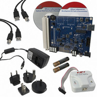
C8051F996-DK 3. Hardware Setup Refer to Figure 2 for a diagram of the hardware configuration. 1. Connect the USB Debug Adapter to the DEBUG connector on the target board with the 10-pin ribbon cable. 2. Connect one end of the ...
Page 3
Software Installation The included CD-ROM contains the Silicon Labs Integrated Development Environment (IDE), 8051 evaluation toolset, optional software utilities, and additional documentation. Insert the CD-ROM into your PC’s CD-ROM drive. An installer will automatically launch, allowing you to install ...
Page 4
C8051F996-DK 5. Software Overview The following software is necessary to build a project, download code to, and communicate with the target microcontroller. 8051 Evaluation Toolset Silicon Labs Integrated Development Environment (IDE) Other useful software that is provided on ...
Page 5
Download the project to the target by clicking the Download Code button in the toolbar. Note: To enable automatic downloading if the program build is successful select Enable automatic con- nect/download after build in the Project build process, the ...
Page 6
C8051F996-DK 5.3. Configuration Wizard 2 The Configuration Wizard code generation tool for all of the Silicon Labs devices. Code is generated through the use of dialog boxes for each of the device's peripherals. Figure 3. Configuration Wizard ...
Page 7
Silicon Labs Battery Life Estimator The Battery Life Estimator is a system design tool for battery operated devices. It allows the user to select the type of battery they are using in the system and enter the supply current ...
Page 8
C8051F996-DK Figure 5. Battery Life Estimator Discharge Profile Editor The Discharge Profile Editor allows the user to modify the profile name and description. The four text entry boxes on the left hand side of the form allow the user to ...
Page 9
The wakeup frequency box calculates the period of a single iteration through the four power modes and displays the system wake up frequency. This is typically the "sample rate" in low power analog sensors. Once the battery type and discharge ...
Page 10
C8051F996-DK 5.5. Keil µVision2 and µVision3 Silicon Labs Drivers As an alternative to the Silicon Labs IDE, the µVision debug driver allows the Keil µVision IDE to communicate with Silicon Labs on-chip debug logic. In-system Flash memory programming integrated into ...
Page 11
Target Board The C8051F996 Development Kit includes a target board with a C8051F996 device pre-installed for evaluation and preliminary software development. Numerous input/output (I/O) connections are provided to facilitate prototyping using the target board. Refer to Figure 7 for ...
Page 12
C8051F996-DK The following items are located on the bottom side of the board. See Figure 8. BH1 Battery Holder for 1.5 V AAA. BH2 Battery Holder for 1.5 V AAA. BH3 Battery Holder for 3 V Coin Cell (CR2032). BH2 ...
Page 13
Target Board Shorting Blocks: Factory Defaults The C8051F996 Target Board comes from the factory with pre-installed shorting blocks on many headers. Figure 9 shows the positions of the factory default shorting blocks. R15 J16 P1.4 J15 GND PORT2 P1 ...
Page 14
C8051F996-DK 7.2. Target Board Power Options and Current Measurement (J10, J11, J17, H2, P2, P3, SW5) The C8051F996 Target Board supports three power options, selectable by the three-way header (J10/J11). Power to the MCU may be switched on/off using the ...
Page 15
System Clock Sources 7.3.1. Internal Oscillators The C8051F996 device installed on the target board features a factory calibrated programmable high-frequency internal oscillator (24.5 MHz base frequency, ±2%) and a low power internal oscillator (20 MHz ±10%). After each reset, ...
Page 16
C8051F996-DK 7.5. Switches and LEDs (J1, J5, J8, J15, J16, SW1, SW2, SW3) Three push-button switches are provided on the target board. Switch SW1 (RESET) is connected to the reset pin of the C8051F996. Pressing SW1 puts the device into ...
Page 17
Expansion I/O Connector (P1) The 96-pin Expansion I/O connector P1 provides access to all signal pins of the C8051F996 device (except the C2 debug interface signals). In addition, power supply and ground pins are included. A small through-hole prototyping ...
Page 18
C8051F996-DK 7.7. Target Board DEBUG Interface (J9) The DEBUG connector J9 provides access to the DEBUG (C2) pins of the C8051F996 used to connect the Serial Adapter or the USB Debug Adapter to the target board for in-circuit ...
Page 19
IREF Connector (J7) The C8051F996 Target Board also features a current-to-voltage 1 k load resistor that may be connected to the current reference (IREF0) output that can be enabled on port pin (P0.7). Install a shorting block on J7 ...
Page 20
C8051F996-DK 8. Schematics 20 Rev. 0.1 ...
Page 21
C8051F996-DK Rev. 0.1 21 ...
Page 22
C8051F996-DK 22 Rev. 0.1 ...
Page 23
N : OTES C8051F996-DK Rev. 0.1 23 ...
Page 24
... Should Buyer purchase or use Silicon Laboratories products for any such unintended or unauthorized ap- plication, Buyer shall indemnify and hold Silicon Laboratories harmless against all claims and damages. Silicon Laboratories and Silicon Labs are trademarks of Silicon Laboratories Inc. Other products or brandnames mentioned herein are trademarks or registered trademarks of their respective holders. ...