DEMOACKIT Freescale Semiconductor, DEMOACKIT Datasheet
DEMOACKIT
Specifications of DEMOACKIT
Available stocks


Related parts for DEMOACKIT


DEMOACKIT Summary of contents
Page 1
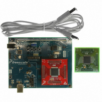
Development Board for Freescale FLEXIS AC MCU Family DEMOAC MCF51AC256 MC9S08AC128 MC9S08AC60 MC9S08AC16 Hardware User Guide Web Site: Support: support@axman.com Supports: www.axman.com ...
Page 2
CAUTIONARY NOTES ..............................................................................................................4 TERMINOLOGY.........................................................................................................................4 FEATURES ................................................................................................................................5 REFERENCES ...........................................................................................................................6 GETTING STARTED..................................................................................................................6 APPLICATION DEVELOPMENT ...............................................................................................6 HARDWARE CONFIGURATION ...............................................................................................6 INTEGRATED BDM............................................................................................................... 6 BDM PORT CONNECTOR ............................................................................................... 7 POWER ...
Page 3
INITIAL FLASH PROGRAMMING ................................................................................... 16 Figure 1: BDM Connector ...........................................................................................................7 Figure 2: PWR Jack....................................................................................................................8 Figure 3: PWR_SEL Option Header ...........................................................................................9 Figure 4: VX_EN Option Header ...
Page 4
CAUTIONARY NOTES 1) Electrostatic Discharge (ESD) prevention measures should be used when handling this product. ESD damage is not a warranty repair item. 2) Axiom ...
Page 5
FEATURES The DEMOAC provides a platform supporting a line of Freescale microcontrollers which are part of the Flexis Continuum. Target microcontrollers mount on plug-in modules ...
Page 6
REFERENCES The following documents should be referenced during application development using the DEMOAC. These documents are available on the MCF51JM128 and DEMOAC web pages (http://www.freescale.com/coldfire). ...
Page 7
The integrated debugger provides power and ground to the target, thereby eliminating the need to power the board externally. Power from the integrated USB BDM ...
Page 8
Figure 2: PWR Jack 2.1mm, center-positive, +V input Applied voltage: +7V to +18V PWR A voltage regulator provides +5V to the target MCU and board ...
Page 9
Figure 3: PWR_SEL Option Header PWR_SEL • • • BDM VR1 PWR_SEL • • • BDM VR1 NOTE: The voltage regulator reference designator at the ...
Page 10
apply an alternate power input, simply remove the cut-trace using a sharp knife. Then either solder a wire to the thru-hole via or install a ...
Page 11
RESET Switch The RESET switch allow the manual application of the RESET* signal. Application of RESET halts the current operation and initializes internal registers to ...
Page 12
Communications The DEMOAC board provides 2 UART ports, 1 IIC port, and 1 CAN port. Serial RS-232 com- munications is support through the integrated BDM. ...
Page 13
Potentiometer A 5k ohm, single-turn, thumb-wheel type, potentiometer at RV1 provides continuous, variable resistance input for user applications. The potentiometer is connected between VDD and ...
Page 14
The DEMOAC applies the MMA7260Q, 3-axis accelerometer for tilt and motion-sense applica- tions. The accelerometer supports 4 user selectable sensitivities - 1. ...
Page 15
MCU_PORT The MCU PORT provides user access to the DEMOAC I/O ports. Refer to the MCF51AC256 or MC9S08AC128/60/16 Integrated Device Reference Manual for signal details. ...
Page 16
TROUBLESHOOTING The DEMOAC is fully tested and operational before shipping fails to function properly, in- spect the board for obvious physical damage first. ...