C8051F912DK Silicon Laboratories Inc, C8051F912DK Datasheet
C8051F912DK
Specifications of C8051F912DK
Available stocks


Related parts for C8051F912DK

C8051F912DK Summary of contents
Page 1
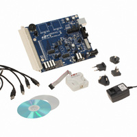
C8051F912 Relevant Devices The C8051F912 Development Kit is intended as a development platform for the microcontrollers in the C8051F91x-C8051F90x MCU family. The members of this MCU family are ...
Page 2
C8051F912-DK 3. Software Overview All software required to develop firmware and communicate with the target microcontroller is included in the CD- ROM. The CD-ROM also includes other useful software. Below is the software necessary for firmware development and communication with ...
Page 3
Party Toolsets The Silicon Laboratories IDE has native support for many 8051 compilers. The full list of natively supported tools is as follows: Keil IAR Raisonance Tasking Hi-Tech SDCC The demo applications ...
Page 4
C8051F912-DK 3.5. Configuration Wizard 2 The Configuration Wizard code generation tool for all of the Silicon Laboratories devices. Code is generated through the use of dialog boxes for each of the device's peripherals. Figure 2. Configuration Wizard ...
Page 5
Silicon Labs Battery Life Estimator The Battery Life Estimator is a system design tool for battery operated devices. It allows the user to select the type of battery they are using in the system and enter the supply current ...
Page 6
C8051F912-DK Figure 4. Battery Life Estimator Discharge Profile Editor The Discharge Profile Editor allows the user to modify the profile name and description. The four text entry boxes on the left hand side of the form allow the user to ...
Page 7
The wakeup frequency box calculates the period of a single iteration through the four power modes and displays the system wake up frequency. This is typically the "sample rate" in low power analog sensors. Once the battery type and discharge ...
Page 8
C8051F912-DK 3.7. Keil µVision2 and µVision3 Silicon Laboratories Drivers As an alternative to the Silicon Laboratories IDE, the µVision debug driver allows the Keil µVision2 and µVision3 IDEs to communicate with Silicon Laboratories’ on-chip debug logic. In-system Flash memory programming ...
Page 9
Using the Keil Software 8051 Tools with the Silicon Laboratories IDE To perform source-level debugging with the IDE, configure the Keil 8051 tools to generate an absolute object file in the OMF-51 format with object extensions and debug records ...
Page 10
C8051F912-DK 5.2. Building and Downloading the Program for Debugging 1. Once all source files have been added to the target build, build the project by clicking on the Build/Make Project button in the toolbar or selecting Project Note: After the ...
Page 11
Example Source Code Example source code and register definition files are provided in the “SiLabs\MCU\Examples\C8051F91x_90x\” default directory during IDE installation. These files may be used as a template for code development. Example applications include a blinking LED example which ...
Page 12
C8051F912-DK 7. Target Board The C8051F912 Development Kit includes a target board with a C8051F912 device pre-installed for evaluation and preliminary software development. Numerous input/output (I/O) connections are provided to facilitate prototyping using the target board. Refer to Figure 7 ...
Page 13
The following items are located on the bottom side of the board. See Figure 8. BT1 Battery Holder for 1.5 V AAA. Use for one-cell or two-cell mode. BT2 Battery Holder for 1.5 V AAA. Use for two-cell mode only. ...
Page 14
C8051F912-DK 7.1. Target Board Shorting Blocks: Factory Defaults The C8051F912 Target Board comes from the factory with pre-installed shorting blocks on many headers. Figure 9 shows the positions of the factory default shorting blocks. R15 J16 P1.4 J15 GND P1 ...
Page 15
Target Board Power Options and Current Measurement (J10, J11, J17, H2, P2, P3, SW4, SW5) The C8051F912 Target Board supports three power options, selectable by the three-way header (J10/J11). The power options vary based on the configuration (one-cell or ...
Page 16
C8051F912-DK 7.3. System Clock Sources 7.3.1. Internal Oscillators The C8051F912 device installed on the target board features a factory calibrated programmable high-frequency internal oscillator (24.5 MHz base frequency, ±2%) and a low power internal oscillator (20 MHz ±10%). After each ...
Page 17
Switches and LEDs (J1, J5, J8, J15, J16) Three push-button switches are provided on the target board. Switch SW1 (RESET) is connected to the reset pin of the C8051F912. Pressing SW1 puts the device into its hardware-reset state. Switches ...
Page 18
C8051F912-DK 7.6. Expansion I/O Connector (P1) The 96-pin Expansion I/O connector P1 provides access to all signal pins of the C8051F912 device (except the C2 debug interface signals). In addition, power supply and ground pins are included. A small through-hole ...
Page 19
Target Board DEBUG Interface (J9) The DEBUG connector J9 provides access to the DEBUG (C2) pins of the C8051F912 used to connect the Serial Adapter or the USB Debug Adapter to the target board for in-circuit debugging ...
Page 20
C8051F912-DK 7.10. IREF Connector (J7) The C8051F912 Target Board also features a current-to-voltage 1 k load resistor that may be connected to the current reference (IREF0) output that can be enabled on port pin (P0.7). Install a shorting block on ...
Page 21
Frequently Asked Questions 1. Should power be turned off when switching between one-cell and two-cell mode? Yes, power must be turned off by placing SW5 in the OFF position when switching between one-cell and two- cell mode. Switching between ...
Page 22
C8051F912-DK 6. What can reduce active supply current? Below are some suggestions for reducing the active supply current: a. Clear all wake-up sources in the PCU0CF register. This will allow the low power oscillator to be disabled ...
Page 23
When the missing clock detector is enabled, why does the MCU reset if I switch from the default system clock (Low Power Oscillator divided smaRTClock divided by 1? Background: —The missing clock detector will trigger a ...
Page 24
C8051F912-DK 9. Schematics 24 Rev. 0.1 ...
Page 25
C8051F912-DK Rev. 0.1 25 ...
Page 26
C8051F912-DK 26 Rev. 0.1 ...
Page 27
N : OTES C8051F912-DK Rev. 0.1 27 ...
Page 28
... Should Buyer purchase or use Silicon Laboratories products for any such unintended or unauthorized ap- plication, Buyer shall indemnify and hold Silicon Laboratories harmless against all claims and damages. Silicon Laboratories and Silicon Labs are trademarks of Silicon Laboratories Inc. Other products or brandnames mentioned herein are trademarks or registered trademarks of their respective holders. ...