C8051F700DK Silicon Laboratories Inc, C8051F700DK Datasheet
C8051F700DK
Specifications of C8051F700DK


Related parts for C8051F700DK

C8051F700DK Summary of contents
Page 1
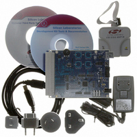
C8051F700 Relevant Devices The C8051F700 Development Kit is intended as a development platform for the microcontrollers in the C8051F70x/71x MCU family. The members of this MCU family are: ...
Page 2
C8051F700- J16 DS3 J8 SWITCH P2.2 P1.1 SW1 SWITCH P2 SILICON LABS J5 C8051F700-TB www.silabs.com Figure 1. Hardware Setup using a USB Debug Adapter 2 DS1 P4 SWITCH P2.3 RESET SW2 J12 VDD DEBUG SWITCH ...
Page 3
PC Software Overview 4.1. CP210x USB to UART VCP Driver Installation The C8051F700 Target Board includes a Silicon Laboratories CP2102 USB-to-UART Bridge Controller (U2). Device drivers for the CP2102 need to be installed before PC software such as HyperTerminal ...
Page 4
C8051F700-DK Silicon Laboratories IDE TM QuickSense Configuration Wizard Figure 2. Silicon Labs QuickSense Studio Software For detailed information on the QuickSense Studio software, please see the QuickSense Studio User’s Guide available on the Silicon Labs QuickSense webpage (www.silabs.com/quicksense) in the ...
Page 5
System Requirements The Silicon Laboratories IDE requirements: Pentium-class host PC running Windows 2000 or later. One available USB port. 4.5. Third-Party Toolsets The Silicon Laboratories IDE has native support for many 8051 compilers. Natively-supported tools are as ...
Page 6
C8051F700-DK Note: To enable automatic downloading if the program build is successful select Enable automatic con- nect/download after build in the Project build process, the IDE will not attempt the download. 5. Save the project when finished with the debug ...
Page 7
Target Board The C8051F700 Development Kit includes a target board with a C8051F700 device pre-installed for evaluation and preliminary software development. Numerous input/output (I/O) connections are provided to facilitate prototyping using the target board. Refer to Figure 3 for ...
Page 8
C8051F700- DS3 J8 C8051F700-TB 8 J16 SWITCH P2.2 SWITCH P2.3 P1.1 SW1 SWITCH P2.0 SWITCH P2 F700 J6 SILICON LABS J5 J4 www.silabs.com Figure 3. C8051F700 Target Board Rev. 0.2 DS1 P4 RESET SW2 ...
Page 9
Target Board Shorting Blocks: Factory Defaults The C8051F700 target board comes from the factory with pre-installed shorting blocks on many headers. Figure 4 shows the positions of the factory default shorting blocks DS3 J8 C8051F700-TB Figure 4. ...
Page 10
C8051F700-DK 6.2. Target Board Power Options and Current Measurement The C8051F700 Target Board supports three power options, selectable by placing a shorting block on J15. The power options are described in the paragraphs below. 6.2.1. Wall Power and Debug Power ...
Page 11
System Clock Sources 6.3.1. Internal Oscillator The C8051F700 devices feature a calibrated internal oscillator which is enabled as the system clock source on reset. After reset, the internal oscillator operates at a frequency of 24.5 MHz (±2%) by default, ...
Page 12
C8051F700-DK 6.5. Target Board DEBUG Interface (DEBUG / P3) The DEBUG connector J9 provides access to the DEBUG (C2) pins of the C8051F700 used to connect the Serial Adapter or the USB Debug Adapter to the target board ...
Page 13
Table 4. Serial Interface Header (J12) Description Header Pins J12[1-2] J12[3-4] J12[5-6] J12[7-8] J12[9-10] 6.8. Voltage Reference (VREF) and Analog Ground Connectors (J13 and J14) The VREF connector can be used to connect the VREF pin from the MCU (P0.0) ...
Page 14
C8051F700-DK 6.11. Expansion Connector (P1) The 96-pin expansion I/O connector P1 is used to connect daughter boards to the main target board. P1 provides access to all of the C8051F700 pins. Pins for VDD and GND are also available. See ...
Page 15
Schematics C8051F700-DK Rev. 0.2 15 ...
Page 16
C8051F700-DK 16 Rev. 0.2 ...
Page 17
C8051F700-DK Rev. 0.2 17 ...
Page 18
... Should Buyer purchase or use Silicon Laboratories products for any such unintended or unauthorized ap- plication, Buyer shall indemnify and hold Silicon Laboratories harmless against all claims and damages. Silicon Laboratories and Silicon Labs are trademarks of Silicon Laboratories Inc. Other products or brandnames mentioned herein are trademarks or registered trademarks of their respective holders. ...